8. BIM models supporting the BIM-based building LCA
8.1. Example buildings’ design principles
To investigate and demonstrate how modelling supports BIM-based building LCA, the project developed two example buildings and their sites: a residential building (Figure 6) and an office building (Figure 7). Both buildings are designed with a wooden and a concrete structure. The buildings are designed according to the Finnish Construction Act and building codes. The design principles emphasise the life-cycle properties of buildings, e.g., multi-purpose usability, adaptability, and access to natural light. Both buildings are modelled as wooden and concrete structures. The structural material versions of both buildings start from identical room layouts. The differences caused by the materials of the structures are therefore reflected in small differences in the floor areas and volumes of the buildings.
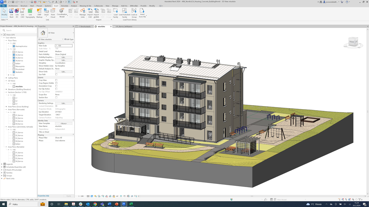
Figure 6. A concrete residential building in Revit.
The residential building is designed to provide housing for residents who may need care services but want to live with or close to their families. The building consists of half of the apartments designed for service housing for families and half of the regular family apartments. The building is narrow in width, and all apartments have windows opening on three sides, allowing good natural light and flexible furnishing. On the ground floor, there is a shared space. Next to the shared space, there is a sheltered outdoor terrace with a pleasant microclimate.
On the basement floor, there is a rentable space that supports services and possibilities for social functions for the residents. The shading structures of the facades are made of recycled materials. Accessible parking spaces are located on the ground floor, with direct access to lifts and apartments. Other parking spaces are in the external car shelter.
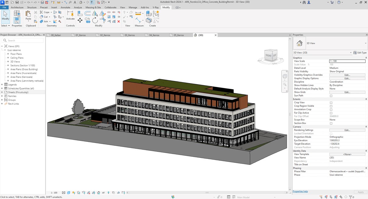
Figure 7. A concrete office building in Revit.
The office building is designed to provide flexible office space and recreational and exercise facilities for the company's employees. MEP and electrical solutions have also been implemented in a way that allows for flexible combining and sharing of spaces. On the ground floor, there is a restaurant, a cabinet space for meetings and a space for an office hub that serves the building but also other teleworking people in the neighbourhood. The three floors with office space can be divided for 1-4 different users. The building’s narrow width provides good natural light to all working spaces. To reduce the heat loads from the sun, a shading system has been designed for the south-west façade.
There is a gym in the garage and a sauna and roof terrace on the top floor. In a post-COVID work culture, the service facilities respond to the need to attract employees back to the office. In the future, if the need for office space in the area decreases, the service spaces will create opportunities to convert the building to other uses (e.g. hotel) during its life cycle. To allow for future flexible use of the site, car parking has also been provided on two levels in a separate building attached to the main building.
8.2. Several design disciplines
Both buildings and their versions consist of several native models and their IFCs: architectural, structural, electrical and heating, ventilation and air conditioning (HVAC) systems. Wood-framed buildings also include sprinkler systems. The design team was led by architects from Huvila Oy. Gravicon was responsible for the structural design, and Granlund was responsible for the HVAC, sprinkler, and electrical design. VTT managed the overall design process, ensuring all design disciplines followed the design schedule and commonly agreed design principles and produced BIM specification documents.
In all design phases of the project, the disciplines carried out the design work solely by modelling. As a result, several model versions were produced (Table 3). All the models are available on the Nordic Sustainable Construction website
Creative Commons license (CC BY-SA 4.0), available from https://creativecommons.org/licenses/by-sa/4.0/deed.en
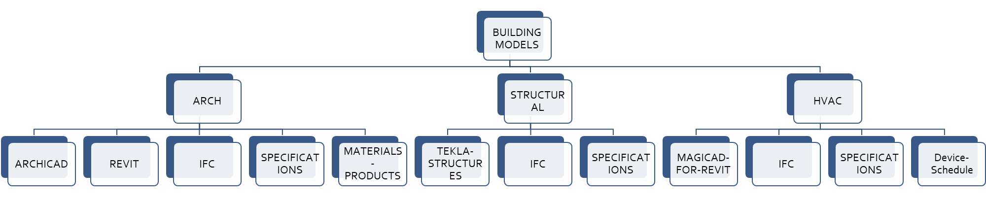
Figure 8. The folder structure of models on the Nordic Sustainable Construction website.
A list of the people who have created the BIM models for this BIM4LCA project can be found in the Appendix C: BIM model authors and BIM file names. The appendix includes the names of the BIM files.
Table 3. BIM models and IFCs produced in the project
Design model | Wooden | Concrete | Site models | IFC files | ||
Architectural building permit models | Residential building in Revit | Office building in Revit | Residential building in Revit | Office building in Revit and ArchiCAD | Residential and office building sites for Wooden and Concrete versions in Revit, Office building site in Archicad | As many as the native models = 10 IFC files |
Architectural as-built models | Residential building in Revit and ArchiCAD | Office building in Revit | Residential building in Revit | Office building in Revit | Residential building site in Archicad | = 2 IFC files |
Structural models | Residential building in Tekla Structures | Office building in Tekla Structures | Residential building in Tekla Structures | Office building in Tekla Structures | = 4 IFC files | |
HVAC models (Wood frame also includes sprinkler -systems) | Residential building in MagiCAD for Revit | Office building in MagiCAD for Revit | Residential building in MagiCAD for Revit | Office building in MagiCAD for Revit | = 4 IFC files | |
Electrical models | Residential building in MagiCAD for Revit | Office building in MagiCAD for Revit | Residential building in MagiCAD for Revit | Office building in MagiCAD for Revit | = 4 IFC files | |
8.3. Two frame material options
Two different frame material options were produced for each building: concrete and timber frame (Table 4). The aim was to keep the buildings' functionality unchanged regardless of the frame material. The material influenced, among other things, the distance between the floors of both buildings. This approach was used to simulate the impact of the frame material options on the LCA.
The buildings’ frame structure is based on prefabricated production. The spaces and built components are organised in the models according to the Finnish interoperability specifications. The Finnish definitions are published on the National Interoperability platform, which provides tools for defining interoperable data content.
Interoperability platform, available from https://dvv.fi/en/interoperability-platform, accessed 29.5.2024.
Table 4. Description of the building types.
Residential building (wooden and concrete structure) | Office building (wooden and concrete structure) |
· Ground floor with service spaces + 3 floors with apartments (half designed for service housing for families, half regular family apartments: window orientation in each to 3 directions) · A basement with storage spaces · A garage · One stairwell with an elevator · Apartment-specific ventilation system · Wooden structure version: Load-bearing wood frame structure walls with wood panel facades · Concrete structure version: Load-bearing concrete walls with brickwork facades | · Ground floor with restaurant /other public functions + 3 floors with flexibly dividable office space (narrow building width for minimising dark room spaces) · A basement with a bomb shelter, employee facilities and storage space · A garage · Two stairwells with elevators · A top floor with a semipublic reservable sauna, roof terrace and ventilation engine room · Wooden structure version: Wooden column and beam structure, wood panel facades · Concrete structure version: Concrete column and beam structure, siding panel facades |
8.4. Building design process
Although the buildings developed in the project are not intended to be built, the project closely simulates the actual design process. The design process started with the architectural design. After the first design versions were completed, the rest of the design team started to develop their own designs with a technical review of the architectural design. This review produced many changes. These changes aimed to rationalise the technical solutions and make the buildings as realistic as possible. At the same time, however, the ambition was to maintain the original architectural objectives.
Once the main principles of the structural solutions and building services had been worked out, the design work moved on to the technical design phase. The team held weekly design meetings to solve small and large design problems in the same way as in real projects. During the whole process, the team also shared the developing versions of their models with each other.
While the technical designers were working on their own designs, the architects were finalising the designs corresponding to the information content of the building permit phase. Once the building permits phase models were ready, the architects started to collect material and product data for the as-built output. This was a deviation from a typical project where final data regarding materials and products is usually provided by the contractors.
8.5. Information content in the two phases of the project
The produced models cover both the building permit phase and the as-built phase. These stages define the information content of the models. Models in this context refer to the set of BIM models and their accompanying material and product descriptions in tabular form. Their interrelationship is explained in the chapter 'Key principles'. HVAC models represent both phases, following the current industry practice. More information on Finnish HVAC standardisation can be found in the external folder HVAC - 0_MEP_standardization_2024.docx.
The models at the building permit stage provide generic material information, which, in practice, are the requirements for product and material selection for the project. The as-built phase models provide more detailed information on selected products and materials. However, it is difficult or impossible to incorporate as-built information directly into IFC models because the contractor responsible for product and material procurement often cannot access the design models. Therefore, the product and material information are recorded in external spreadsheets (in this project, they are in Excel sheets in the folder “MATERIALS-PRODUCTS” of the Nordic Sustainable Construction website
Technically, material data could be included in an IFC model, but different software have slightly different ways of assigning materials to components, and the information is not consistent between components, even in models created with the same software. Another reason for separating material and product data into a separate file is in the process. In the construction phase, at the latest, responsibility for products and materials is transferred to contractors (of which there are several in different domains), while responsibility for the model’s geometry remains with the designer.
By splitting the data into different records, the production of data does not create additional work for the parties involved. It is essential that in both BIM models and external records, building components have consistent type identifiers that can be used to link model components and external product and material data. The external record should be in a machine-readable format. This project developed a standard Excel spreadsheet to meet this requirement, which is adopted for all models produced in the project. Nevertheless, it would be more feasible for the data to be in an international standard format. However, no such international standard was yet implemented at the time of this project.
Geometrically, the models of the building permit and as-built phases are very close to each other. The architectural model for the as-built phase typically has some building services enclosures added, and possibly the dimensions of some walls or other structures have been updated. However, major changes are not even possible for residential homes for sale after sales activity has started. Further, the as-built phase models do not require any additions to precast element groups that were not included at the building permit stage.
8.6. Modelling standards
The main standards guiding the modelling have been EN 15978 (Sustainability of construction works. Assessment of environmental performance of buildings. Calculation method) and EN ISO 16739-1 (Industry Foundation Classes or IFC for short). At the time of the project design and modelling work, an unpublished review version of EN 15978 was available. The version of EN ISO 16739-1 published in 2018 was mainly used, but also the version published in the first half of 2024, where applicable.
The data structure of the models is mainly governed by EN ISO 16739-1, i.e. the IFC standard. IFC has established itself globally as an open, software-independent data structure for model-based data exchange. The National Archives of Finland has adopted the IFC data structure in STEP format as an official archiving format. It will, therefore, be the data format that the building authorities will accept for BIM models under the updated Building Act from the beginning of 2026.
In Finland, IFC has been used in construction projects for two decades. However, the industry has not been able to harmonise the data content of IFC models, and there have been large variations between projects and design offices. This has complicated the automated extraction of data from the models. The machine readability requirements of the revised Building Act have mandated the standardisation of data content so that models can be used widely and in a standardised way, for example, in LCA calculations.
All BIM models in the project have been developed according to the principles published in 2012 in the Finnish Common BIM Requirements (COBIM2012). These requirements are based on the IFC standard. The breakdown structure of the models follows the system categories of EN 15978. Where necessary (e.g. furniture, railings and room areas), this standard approach has been supplemented by the requirements under the new Finnish Building Act as defined, for example, in the national RAVA3pro project. The EN 15978 categories correspond well to the IFC classes and the Finnish Talo2000 classification, so its use did not lead to any particular changes in the modelling. However, particular attention was paid to the type labelling of the elements in the model.
The national codes are recorded in the IFC models and may be employed through the material inventory lists in LCA software as per existing conventions. Although the example models are based on the Finnish code definition, the same data processing principles can be applied using different international classification and coding systems.
IFC 4.0.2.1 (ISO 16739-1:2018) does not provide sufficient coverage for identifying MEP product components using IFC standard entities and enumerations. For this reason, the identification of product components was implemented using national MEP product nomenclatures (see the folder HVAC - 0_MEP_standardization_2024.docx). The data structure, i.e., the feature sets and properties, had to be defined on a product-by-product basis. Each product-based property set, property, and property value were defined separately for each object, even if it represented type data.
The content of all models, including the standards and classification systems used, is documented in model-specific BIM specification documents following COBIM2012 requirements. The various disciplines’ example BIM specification documents are listed in Appendix D: Example BIM specification documents.
8.7. Classification systems
The modelling requirements proposed in this report are independent of a particular classification. The classification system used has no technical impact on transferring element data to the LCA software. Still, it facilitates the grouping of quantity data from the IFC model according to the needs of the LCA calculation. Therefore, the classification system should provide an equivalent for the EN 15978 categories.
The BIM4LCA project developed together with a parallel project (Task 2“Data for LCA”) a comparison table comparing the consistency of prEN 15978 and ISO 16739-1:2024 (IFC 4.3) in terms of design model data content (see Appendix A: prEN 15978 comparison to IFC 4.3 (ISO 16739-1:2024)). The BIM4LCA project also included a comparison between prEN 15978, IEC 81346-12 classification, the Swedish CoClass classification, the Talo2000 classification and the interoperability code sets and ICMS classification system (See Appendix B: Comparison between prEn 15978, ISO 81346-12, CoClass, Talo2000 and ICMS). The first version of the comparison was published in the final report of Task2 “Data for LCA” project.
See the report here: Nordic view on data needs and scenario settings for full life cycle building environmental assessment available: https://www.nordicsustainableconstruction.com/Media/638542191749462744/Nordic%20view%20on%20data%20needs%20and%20scenario%20settings%20for%20full%20life%20cycle%20building%20environmental%20assessment.pdf, accessed 25.6.2024
The comparisons (Appendix A and Appendix B) show that a comprehensive mapping between the different classification systems, the IFC and the national code systems, is possible. From a BIM modelling context, EN 15978 contains, with a few exceptions, an adequate breakdown of the content of design models. When modelling for LCA purposes, the BIM4LCA project recommends that EN 15978 is the common starting point for the elemental breakdown structure of models for LCA calculation.
8.8. Models as proprietary formats of the design software
The BIM4LCA project produced a large number of models using different design software. These models can be used to develop and disseminate the project results to the various stakeholders. As a result of the project, all models are shared, both in the open file format (IFC4) according to ISO 16739-1:2018 and in the proprietary formats of the software used to create them (Finnish versions of Revit, MagiCAD for Revit, ArchiCAD, Tekla Structures). There may be some limitations in the software's proprietary models due to the way the software embeds various libraries or utilities that cannot be distributed with the models. Further use may, therefore, require the missing libraries to be re-linked. The IFC models do not have similar shortcomings.
A suitable software is needed to open the models. There are several freeware tools available for examining IFC models. However, commercial software may be needed for more extensive use of the models, such as reporting quantity data. Opening and viewing proprietary format files always requires commercial software licences with the same or newer version of the software and, in many cases, a correct language pack (in this case, Finnish). This means that IFC models are accessible to a wider range of end-users.
Proprietary format models can be useful for data producers, mainly designers, as they can explore solutions for generating data content from models available in proprietary formats in the design software. On the other hand, data users can utilise IFC models as a reference to ensure the correctness of data content in real construction projects. Models in both formats can also be used for presentations and training. The BIM models created in this project are expected to be widely used because BIM models of similar quality, well-created and "correctly" designed for real buildings are unavailable.
From the point of view of LCA calculation, the most important document related to the models is the external spreadsheet (i.e., the Excel sheets in the folder “MATERIALS-PRODUCTS” of the Nordic Sustainable Construction website), which records the properties of the element types in the model, such as material layers and product information. The project also published a BIM specification document for each IFC model. This document captures the key aspects of the model, such as the elevation of floors, the coordinate system, the classifications used, and related external documents.
For further use of the models, it should be noted that they have been developed primarily according to the principles of the BIM4LCA project and have been used to verify the principles of this project. The models are certainly not flawless in all respects; it would be very time-consuming to produce them completely error-free, which was not possible within the timeframe of this project. Furthermore, the plans have not been thoroughly examined from a technical point of view, nor, for example, have the structural solutions been calculated or otherwise structurally dimensioned in detail. However, as part of the project's final outputs, the models will also be published in the proprietary formats of the design software. They can be refined in future development projects to meet additional needs.
8.9. Use of IFC for quantity data
Although the BIM4LCA project has produced proprietary BIM models, the primary intention in building LCA is to use the IFC versions of the models. The necessary quantity data can be read from them using a variety of software, some of which are even free. Furthermore, the data contained in the models is used in the same way regardless of the software used to create the model.
Each model is accompanied by a spreadsheet that accommodates the properties of the element types in the model, such as material and product information. This spreadsheet is used in parallel with the IFC model. The quantity data of building elements by type is captured from the model, and the material and product data for each type are read from the spreadsheet. The data is then aggregated in the LCA software. The material and product data in the IFC models are not intended to be used in the LCA calculation.
The primary way to generate the quantity data from the models is to read it from the geometry of the components in the model. This ensures that the data format (volume, area, length, number of pieces) and level of detail match the data usage requirements. Exceptions are HVAC and electrical models, where the quantity data is stored in standard properties in the design software (see BIM specifications for HVAC and electrical models for more information). The architectural models also include QTO properties attached to each element, which contains the quantity data generated by the proprietary software. If these are used, it should be noted that the author of the model is not responsible for the quality of the data as they are automatically generated by the software.
To summarise, the process of using quantity data and product and material data in LCA calculations is as follows: The designer creates a model according to the design and ensures that the geometry of the models is correct and that all model elements have a type identifier. The designer exports the model in IFC format. At the building permit stage, the designer creates an external record in which the material and product information for each element type is entered to the level of accuracy known at that time. During the construction phase, the responsibility for updating the data in the external record is transferred to the contractors. The LCA expert generates the quantity data from the IFC model and combines it with the material and product data in the external record in the LCA calculation software using the type identifiers. The emission data for materials and products can be linked either in the external record or LCA software.