1. BIM-based building LCA process
A building information model (BIM) typically contains geometrical and alphanumerical information on the employed building products. During a construction project, different design fields produce BIM models: depending on the design stage, there may be an architectural model, a structural model, and an HVAC and electrical model. All these models contain quantity information that can be employed in building life cycle assessment (LCA) to assess embodied emissions. Figure 1 depicts different stages of data flow required to convert BIM data to usable LCA results.
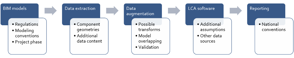
Figure 1. The phases for using BIM for building LCA
The BIM contents were not designed originally with LCA in mind; thus, there are many issues regarding data usability in the current state of modelling. These are related to, for example, reliability in quantity take-off, data specification in property sets, object labelling and model coordination. This work establishes guidelines for how BIM models can be used more in LCA calculations. This is done to support existing BIM modelling conventions and specify minimum requirements for additional information from an LCA point of view. Minimum additional information content in the models and other documentation conventions that support data retrieval from supplementing sources are specified. Best practices are established on how the BIM information can be amended and how overlapping between BIM models is handled.
Figure 2 establishes the steps required to transform the status towards automated BIM-based LCA. As more steps are taken, increasing demands arise on data quality, availability, and the amount of modelling work, among other things. This proposed process aims to take the first step in enabling reliable material take-offs for LCA purposes and establishing conventions on data processing. Further automation is left for the future. The first and second steps are likely to be reached rather quickly. However, to reach the full automation step may take several years due to required integrations with authority systems in countries.

Figure 2. Steps towards automated building LCA
1.1. Key principles for BIM-based embodied emissions calculation
BIM-based embodied emissions calculation as part of a building life cycle assessment (LCA) requires that the type data (products and materials), quantities (dimensions) and function in the building (e.g. external wall, intermediate floor) are correctly modelled in the building information model (BIM). Defined entities and properties should be specified in the BIM specification document so that the background information for the model is available.
One of the basic features of a three-dimensional, BIM-based design model is that it produces quantity data with a high degree of accuracy. The degree of accuracy of the data that can be read from the model depends on the precision of the modelling and the modelling approach. However, the coverage of the models is more important. For example, if the model is missing 10% of the walls, the accuracy of modelling a single wall is no longer relevant. The extent of the elements in the model should correspond as closely as possible to the object to be built.
However, it is not worthwhile or possible to model everything. This depends on the technology used, the design phase's information content, and the modelling resources. For example, it can be very time-consuming to include all equipment in a model compared to listing them in a spreadsheet. In this case, the benefits achieved are not in balance with the time and cost involved. On the other hand, not all equipment and materials are known precisely, especially in the early stages of a project, so it is not even possible to model them. To make reliable use of the quantitative information from the models, it is necessary to know what has been modelled on them and, on the other hand, what information needs to be sought elsewhere.
The IFC standard data structure would allow material and product information to be included within the IFC model. However, there are two problems with this. The technical problem is that the most popular software tools used for BIM-based design do not support storing the type-based design data, i.e. the planned products and materials, in the design models. Some of the data would, therefore, be outside the model in any case.
The second, more significant problem relates to the process. During the construction phase, the designer is still responsible for updating the BIM model, but the contractors manage the type data for as-built products and materials. These parties often do not have a contractual relationship to take responsibility for updating the type data in the design model. To ensure the integrity of the data, it is therefore advisable to hold the contractor responsible for data management. The key between the element in the design model and the material and product catalogue maintained by the contractor is the element type identifier.
To link type information maintained in non-model records to elements in design models, type records must be in a machine-readable format. The simplest way to store type data is to use spreadsheet software. However, any spreadsheet format is not machine-readable; it must be standardised. In this project, a spreadsheet in Excel format was developed. It was programmatically converted into a structured XML format and then back to the original Excel spreadsheet format (roundtrip). This proof-of-concept implementation was intended to ensure that a simple spreadsheet, which does not require any special software investments by designers or contractors, can maintain machine-readable data linked to design model elements. However, as mentioned above, the format of a spreadsheet must be very formal and its content should be able to be automatically converted into a structured data model and vice versa.
Figure 3 illustrates the principles of typing elements in architectural design BIM models. Each element shall be defined with the correct IFC class, predefined type, and required properties in the design model. This information can be used to filter the IFC model by element group, making it easier to organise and check the information that can be read from the models.
Each building and product element type in the IFC model is assigned a project-specific type identifier (e.g., US-1). These type identifiers allow the elements to be linked to external material and product data maintained in a machine-readable format, e.g., in the spreadsheet described above.
Three-dimensional IFC elements, corresponding to real building and product elements, can be used to generate the quantity data for each element. Depending on the elements, the quantities can be read from the model as lengths, areas, volumes, or numbers of elements.
The quantity data of the IFC model are transferred to the LCA calculation software. However, it should be noted that the IFC model contains quantitative data only for the elements to be implemented. Waste materials, formwork, supports and other temporary structures must be considered separately. In addition, the LCA software shall contain quantitative estimates for elements not included in the design model.
The project-specific type identifiers in the IFC model can be used in the LCA calculation software to link the breakdown structure and product data for each element.
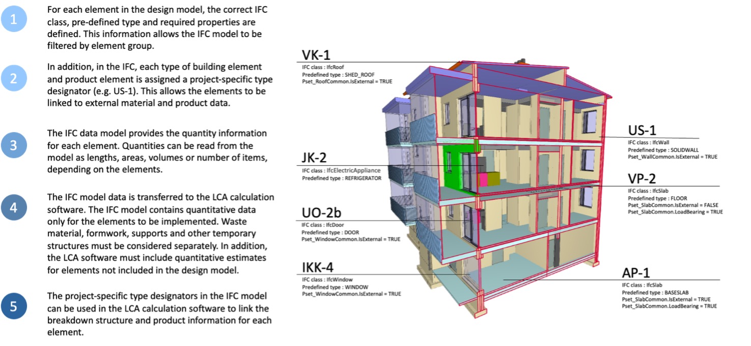
Figure 3. Use of the IFC model to calculate the carbon footprint of a building
1.2. Scope of Nordic climate declarations
Regardless of the differences in assessment methods (e.g., building parts to be included) between the Nordic countries, the basic requirements and principles for modelling are the same. Table 1 displays a comparison of scopes included in assessment methods in Nordic countries.
The national assessment methods regulate system boundaries and the level of detail in reporting on building life cycle assessments. The scope of the assessment methods varies between countries. This BIM to LCA process description intends to enable better data flow from the models to the LCA calculation, regardless of the data content and handling of the actual LCA calculation. Table 1 displays the scope of the assessment methods for reporting and calculation. The national building part labelling is required to be provided as information in a suitable information field. Reporting with the national building part labelling enables, e.g., the assessment of the impacts of using different materials in building parts.
Table 1. Coverage of national assessment methods.
Denmark | Estonia | Finland | Iceland | Norway | Sweden | Europe | |||
Included building parts | BRsB | Proposed draft method for climate declaration (2021) | Climate declaration | Climate declaration proposal (under development) | TEK17 | Climate declaration (2022) | Limit values 2025 Climate declaration 2027 (Boverket's proposal) | LEVEL(s) | |
Site preparation | - | - | Soil stabilisation and site reinforcement elements | - | - | - | Reported from 2027 | ? | |
Substructure | Foundations | x | x | x | x | x | x | x | x |
Piling | x | x | x | x | x | - | Reported from 2027 | ? | |
Basement walls | x | x | x | x | x | x | x | x | |
Ground floor structure | x | x | x | x | x | x | x | x | |
Superstructure (external elements) | The frame (columns and beams) | x | x | x | x | x | x | x | x |
External walls, facade | x | x | x | x | x | x | x | x | |
External doors, windows | x | x | x | x | x | x | x | x | |
Balconies | x | x | x | x | - | x | x | x | |
Roof structures | x | x | x | x | x | x | x | x | |
Superstructure (internal elements) | Internal walls, load- and non-load bearing | x | x | x | x | x | x | x | x |
Floor slabs | x | x | x | x | x | x | x | x | |
Internal doors | x | x | x | x | x | x | x | x | |
Stairs and ramps | x | x | x | x | - | x | x | x | |
Internal finishes | Wall and ceiling interior finishes and coverings | x | x | x | x | x | - | x | x |
Flooring materials | x | x | x | x | x | - | x | x | |
Suspended ceilings | x | x | x | x | x | x | x | x | |
Lifts and escalators | x | x | x | x | - | - | only for building types in Group 1 | x | |
Electricity system | - | x | - | x | - | - | only for building types in Group 1 | x | |
HVAC systems | x | x | x | x | - | - | only for building types in Group 1 | x | |
Building services | Renewable energy systems | x | x | x | x | - | Only building integrated solar panels | All panels in 2025 | x |
Water system | x | x | x | x | - | - | only for building types in Group 1 | x | |
Sewage system | x | x | x | x | - | - | x | x | |
Other systems (e.g., firefighting) | - | x | x | x | - | - | only for building types in Group 1 | x | |
External works | Only if included in the area definition | - | only external structures in the yard | - | - | - | - | x | |
Furnishing | Fixed furniture | - | - | x | - | - | - | only for building types in Group 1 | x |
User furniture | - | - | - | - | - | - | - | - | |
Floor area | Heated net floor area | - | x | x | - | - | - | - | - |
Gross floor area | - | - | - | x | x | x | x | x | |
Reference area, heated gross floor area | x | - | - | - | - | - | - | - | |
Source: Nordic Sustainable Construction, 2024
1.3. Organisation of data
Quality assurance can be divided into the validation of the usability of information in the BIM and the validation of the assessment results. The quality assurance follows the requirements for calculation and reporting. The BIM is prepared in line with the BIM requirements, and the information is precise, correct, and informative. Defined entities and properties are disclosed in the BIM specification document for easy access to information regarding the model. The availability of information supports the quality assurance and validation of correctness and analysis of uncertainties in LCA, which impacts assessments made during an early phase of the project.
It should be noted that the classification of building elements varies at the national level. What all classification systems have in common is that they tend to group building elements into logical categories. However, these logical categories can differ depending on the intended use.
One misconception is that the IFC standard (ISO 16739-1) is a classification system. However, this is not the case. IFC is a system of classes, not a classification system. This is not a semantic difference; it is a fundamental difference. A classification system typically describes a category of a building component in one dimension. A component defined by the IFC can implement the requirements of several different categories and classification systems simultaneously, depending on the attributes of the IFC entity. On the other hand, an IFC component is not independently associated with any particular category of the classification system. A classification system expresses a need that can be met by an IFC component.
Although classification systems are inherently perspective-dependent, they share significant similarities. This project aims to exploit these similarities and transform their needs into IFC standard specifications, producing a generic specification that can be adopted by any national classification system.
The system boundary for building life cycle information is set in the International Standard ISO 21930 and European Standard EN 15804/15978, which set out a common life-cycle model for building and construction works. The system boundary is common for all assessment methods, although national assessment methods differ in which life cycle stages are included in the assessment. ISO 16739-1 is the set standard for Industry Foundation Classes (IFC) for data sharing in the construction and facility management industries.
1.4. Scope and purpose of this work
This instruction describes the process of extracting quantity data from building information modelling (BIM) to calculate and report emissions of materials in life cycle assessment (LCA). The aim is to suggest improvements in BIM models, to better support, optimise and unify life cycle assessments across the Nordic countries, and to unify and streamline the LCA calculation process itself. The work focuses on the method that enables the calculation of embodied emissions; the operational emissions are not extracted from the BIM models and are thus not in the report's scope. The LCA calculations may be based on the enhanced information take-offs as described in this document; the actual calculations themselves will be performed according to the national guidelines and are not within the scope of this work.
1.5. Possible pathways from BIM to LCA
There are two major pathways for calculating the life cycle effects of building components from BIM models. Domain-specific carbon calculation plugins provide one pathway. These plugins have been developed for various design software, such as Tekla Structures, Autodesk Revit and ArchiCAD. These tools are useful as they can give planners or designers instant feedback about GHG emissions, for example, when comparing alternative design solutions. The other pathway leads to a complete LCA for an entire building, which requires data beyond what is available in any single design software. Therefore, quantity take-off from BIM and import to an LCA tool is preferable for required normative calculations. This document focuses on the latter pathway.