3. Electrostatic Precipitator & Catalyst: Secondary Measures
Wood stoves have long been cherished for their ability to provide warmth, comfort, and a cozy atmosphere. However, their contribution to harmful gaseous and particulate emissions has raised concerns about their impact on environment and public health. Implementing secondary measures has emerged as an important strategy in response to these challenges to mitigate emissions from wood stoves. Secondary measures encompass the incorporation of devices designed to capture and reduce emissions after their generation during combustion. Examples include particle filters, electrostatic precipitators, catalysts, scrubbers and so forth. These devices are installed within the stove's exhaust system to trap pollutants before they are released into the atmosphere. The most relevant performance indicator is the pollutant removal efficiency, which can easily be found by measuring pollutant concentrations before and after the device is put in place.
The two main and most mature secondary measures for mitigating wood smoke are electrostatic precipitators and catalytic converters, as described in the following two chapters. German and Swiss producers dominate the production of such devices, as these countries were the most active early adopters of this technology. Other, less established technologies, such as packing technology, electric soot collectors, flue gas scrubber, and additives, are currently being tested.
3.1. Electrostatic Precipitator
Description Of Technology
An electrostatic precipitator (ESP) can be a secondary end-of-pipe measure to reduce emissions from solid fuel combustion, such as wood in wood pellet stoves. Solid particles, that is, ash, soot, and fine organic and mineral particles, can be separated from flue gases with an ESP by charging them electrostatically before the smoke leaves the flue gas pipe.
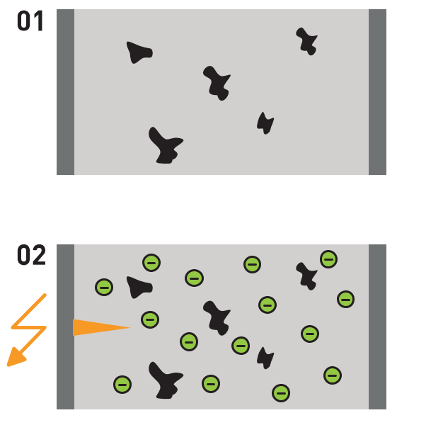
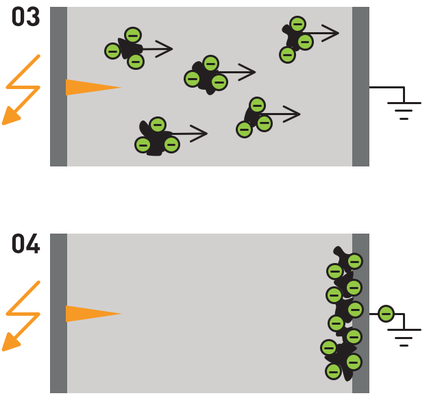
Figure 6: (left) Typical principle of particle separation in wood stove ESPs; example from (OekoSolve, 2023)
An electrode is placed in the flue gas pipe as a metal wire mesh or a rod. A DC voltage of several tens of kilovolts is applied to it with a high voltage generator, releasing free electrons, of which some charge the passing-through particles. The strong electrical field around the electrode pushes the charged particles and remaining free electrons towards the surrounding positively charged metal pipe or wall of the flue gas pipe. Figure 6 illustrates the physical principle of an ESP.
Besides the wet flue gas volume flow and the collecting electrode’s effective surface, the particle migration velocity is also essential. The migration velocity depends on the electrical conductivity of particles, flue gas temperature, flue gas composition, particle size, and the effective electric field intensity (Nussbaumer et al., 2009). The ESP design for wood stove applications typically aims at flue gas velocities between 1.0 and 1.8 m/s between the electrodes (Strauss, 2016); this is about 10 times higher than in larger industrial ESPs. For particles smaller than 100 µm, high separation efficiencies are achievable, as illustrated in Figure 6 (right). However, particle sizes between 0.2 µm and 0.5 µm show minimum separation efficiency because the dominating separation mechanism transitions from impact ionization (dominant for particle sizes > 1 µm) to Brownian diffusion of ions (dominant for particle sizes < 0.1 µm; Nussbaumer et al., 2009). ESPs today are state-of-the-art for large industrial applications. Application of such devices in small-scale appliances, especially stoves, is increasing since emission limit values have become more stringent in recent years. Compared to fabric baghouse filters, an important advantage is the low pressure drops of ESPs that allow unproblematic operations under natural draught conditions. However, temperatures are also important and should generally range between 120°C and 180°C to avoid flue gas condensation. Combustion quality is essential since the separation efficiency of ESPs differs between mineral particles, tar, and soot. Soot and tar can cause problems, either by sticking on the electrodes (tar) or by re-entrainment of particles into the flue gas flow (Lauber and Nussbaumer, 2010). The application of ESPs in manually operated room-heating appliances faces several challenges: minimising noise from sparking; avoiding contamination such as chimney agglomerations or release of flakes (~5 mm); deciding whether to place ESPs in the chimney system or integrate them in the room-heating appliance; addressing high voltage in a living space; ensuring electrode placement in integrated systems allows for good accessibility and suitable temperature levels during operation; and combining ESPs with secondary technologies such as catalysts for PM emission reduction, focusing on gaseous emission reduction.
ESPs as a retrofit solution have two variants: placed (a) at the mouth of the chimney or (b) directly in the flue gas pipe right after the appliance, as illustrated in Figure 7. The issue of installing an ESP in the flue gas duct can be solved in different ways: either by making an opening in the chimney where the ESP is then placed and fastened with a sealing ring and tension strap or with a T-piece in which the ESP is integrated. Some producers can provide such ESPs (e.g., OekoTube Inside model [OekoSolve, 2023], Kutzner + Weber Airjekt model [Kutzner und Weber, 2023], as shown in Figure 8b).
Cleaning of ESP systems is either automatic, semi-automatic, or manual. In most cases, the cleaning relies on sweeping the chimney at regular intervals and then cleaning the electrode at the same time. Semi-automatic cleaning is mechanical—physically removing the collected particles from the electrodes and then removing them from the device. Fine particles can be removed in several ways: with a built-in brush, a magnetic vibrator attached to springs on the inner wall, or water injected through a nozzle system. The fine particles or slurry in the case of water injection are then collected in a pan, which the user must empty manually. It is uncertain whether the residues should be disposed of as waste or not, mainly due to PAH up-concentration when flue gas and particles pass through the ESP reactor (see page 21). Sometimes, the automatic cleaning must be started manually (Obernberger and Mandl, 2011). Fully automatic cleaning means that no manual operation is necessary to keep the device operating as intended for periods of months or years.
The OekoTube (OekoSolve, 2023) system was developed in Switzerland in 2006 and has constantly improved over the years. The OekoTube-Outside (see Figure 8a) is designed and suitable for all wood stoves with a capacity below 50 kW. It is either mounted on top of the chimney or inserted next to the wood stove with the ESP OekoTube Inside solution. It is suitable for most small-scale room heaters, such as open fireplaces, free-standing wood stoves, coal stoves, and central heating systems fueled with wood logs, shavings, or wood chips. It has been proven and officially tested to have a 70%–95% particle removal efficiency and can be fitted on any chimney. The device is manually cleaned through chimney sweeping. The maximum power consumption is 30 W, with a standby power of less than 1 W, at 230V AC. It can support flue gas temperatures up to 400°C.
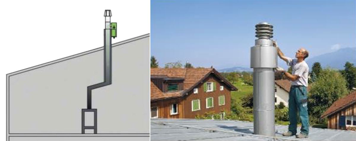
Figure 7a: ESP fitted at the mouth of the chimney
Figure 7b: ESP fitted in the flue gas pipe (three variants)
A Danish producer, Exodraft (Exodraft a/s, 2023), uses electricity to burn off the particles (the nature of emissions being undocumented) collected on a wire mesh at given intervals. In addition, the producer has included a chimney fan at the device outlet to ensure enough draft, enhance all combustion phases, and reduce indoor smoke. This is the only appliance on the market with this self-cleaning solution combined with a chimney fan. Intentionally, the device was supposed to treat diluted flue gas. However, this function has not yet been incorporated. Figure 8c shows the device.
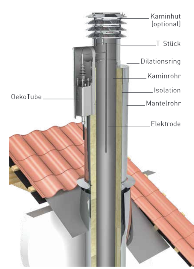
Figure 8a: OekoTube by OekoSolve
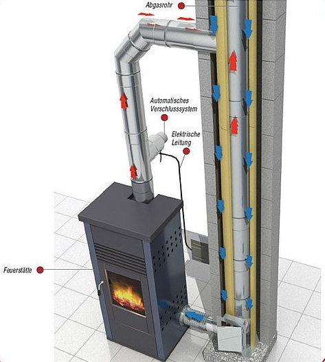
Figure 8b: Kutzner und Weber Airjekt 1 model
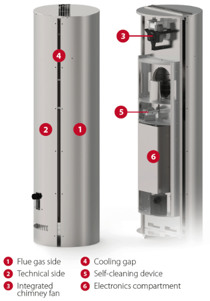
Figure 8c: the Exodraft solution
Cheminées Poujoulat (Cheminées Poujoulat, 2023), one of the largest chimney producers in Europe, offers a particle filtration solution based on the OekoTube product, both as a retrofit and as new installations. Figure 9 shows three variations of this solution.
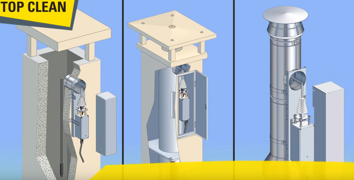
Figure 9: Three variations of the Poujoulat ESP solution
In case of manually cleaned ESP systems, the particles collected on the positive electrode surface must be removed regularly by chimney sweeps. Many modern ESP devices continuously measure the distance between the electrode and chimney wall and pass signals when maintenance is required. The cleaning frequency and maintenance strongly depend on the type of stove, the ash residues from the fuel, the firing behavior, and the firing frequency. This frequency is estimated to be once or twice a year (Obernberger and Mandl, 2011).
ESPs can be applied on all types of domestic wood appliances: fireplaces, stoves, and boilers. However, installing an ESP in flue gases with a lot of lipids is not recommended due to the increased risk of a chimney fire, such as in flue gases from ovens used in restaurants. When the ESP is installed, the transformer creating the high voltage is adjusted according to the features of the appliance and the chimney. If the appliance is replaced later, for instance, by a newer appliance, the transformer has to be adjusted accordingly, and the ESP can continue to operate as before.
For ESPs installed as a retrofit at the chimney outlet, the chimney diameter must have certain dimensions, which will depend on the manufacturer and the desired model. If the diameter is too wide, the removal efficiency will be low. The top of the chimney can be made smaller or narrower if necessary. In addition, ensuring the proper functioning of the ESP has some technical constraints:
- To avoid damage to the ESP, the entering flue gas temperature should not exceed 250°C–400°C, with slight variations between different products.
- The flue gas pipe must include a straight vertical duct of 38–160 cm, depending on the ESP type. This is the length of the ribbon that acts as an electrode and the surface needed to charge all types of fine particles. The longer the remaining pipe after the ESP, the finer the particles deposited on the chimney walls. In addition, collecting fine particles at the bottom of the chimney should also be possible.
- For pellet stoves and pellet boilers, a straight vertical piece of 50 cm chimney is enough because the wood input is controlled and the surface needed to electrostatically charge the particles is smaller.
- Chimneys protruding over 1.5 m above the flat or sloping roofs complicate the installation and maintenance of the system due to the poor accessibility for the installer and the chimney sweep. This concerns most chimneys, and in these cases, the installation will require the use of an aerial work platform. Chimney cleaning can also be done from below.
For ESPs installed in the chimney shortly after the appliance,
- the chimneys must be made of a positively charged material to attract the negatively charged particles. Metal chimneys are suitable for this, but ceramic flue gas channels and masonry chimneys may also work provided they are earthed;
- it must be possible to install the ESP in an easily accessible and visible part of the flue gas chimney, meaning that this configuration can be used only for boilers and stoves where the flue gas chimney is accessible. For difficult to reach flue gas ducts, such as in built-in stoves, using an inspection hatch may be necessary. In addition, there must be a straight vertical duct of at least 50 cm for pellet stoves and pellet boilers; and
- the ESP in the flue gas pipe is only partly suitable for old solid-fuel boilers and stoves due to the possible condensation of tar on the electrode (Obernberger and Mandl, 2011).
The environmental benefit of an ESP is that the particles that can be electrically charged, such as soot and organic and mineral fine particles, can be removed, but it does not affect the flue gases. The reported removal efficiencies vary widely, ranging from 11% to over 90%. This wide range is partly due to dust agglomeration on the walls—later coming loose and being re-emitted—and partly due to the fact that combustion conditions, appliance brands, and duration of the tests often differ. The TU Graz survey (Obernberger and Mandl, 2011) on ESPs for residential biomass combustion in IEA Bioenergy Task 32 member countries reviewed several sources to assess removal efficiencies of ESP devices and provide valuable independent insights on the state-of-the-art of these devices. Table 2 summarises the removal efficiencies of different ESP devices according to various sources, including Greet et al. (2020).
Table 2: Overview of fine particle removal efficiencies of different ESPs
Name of ESP | Installation | Combustion appliance | Average removal efficiency for fine particles | Type and duration of test | Cleaning method | Source information |
Residential ESP | Chimney | Old-wood stove Old-wood stove Multi-stoker boiler Modern stove Old stove | 54%–61% 85%–99% 80% 69% 55% | Field, 61 days Lab, 250 minutes Lab, duration unknown Field, 4,300 hours Field, 4,300 hours | Manual | TU Graz |
Carola-KIT | Flue gas pipe | Modern stove Wood pellet boiler | 87% 82% | Lab, duration unknown | Semi-automatic | TU Graz |
Zumikron | Flue gas pipe | Wood boiler Modern/old stove | 41% 17% 11% | Field, 545 hours | Manual | TU Graz |
OekoTube | Chimney | Modern pellet boiler | 97% | Lab, 5 hours | Manual | TU Graz |
Bosch | Flue gas pipe | Modern pellet boiler | 70% | Lab, 860 hours | Semi-automatic | TU Graz |
RuFF-Kat | Chimney | Modern wood boiler | >70% | Lab, duration unknown | Semi-automatic | TU Graz |
AL-Top Schräder | Flue gas pipe | Modern wood boiler | 48%–82% | Lab, duration unknown | Semi-automatic | TU Graz |
SF20 – Spanner | Flue gas pipe | Modern/old wood boiler | 60% 25% and 80% | Field, 410 hours Field, 2,900 hours | Semi-automatic | TU Graz |
Airbox | Above combustion chamber | Wood stove | 60%–80% | Lab, duration unknown | Manual | TU Graz |
Kamin- Feinstaubkiller | Chimney | Old wood boiler | 64% | Lab, 30 hours | Semi-automatic | TU Graz |
OekoTube | Flue gas pipe | Modern stove | 34%–55% | Lab, duration unknown | Manual | Divi-Divi-VITO |
Residential | Chimney | Old stove Modern stove | 55% 69% | Field, duration unknown | Manual | (Hartmann et al., 2010) |
SF20 Spanner | Flue gas pipe | Pellet boiler | 80% | Field, duration unknown | Semi-automatic | (Hartmann et al., 2010) |
Exodraft | Chimney | Modern/old stove | 70% of total PM mass, 95% reduction in PM number | Lab, several years | Automatic | Exodraft/DTI (Exodraft a/s, 2023) |
Airjekt 1 NW 130-250 mm | Flue gas pipe | Modern/old stove | Separation rate possible up to 95%, Filtration efficiency >50 % | Lab, several years | Manual | (Kutzner und Weber, 2023) |
From Table 2, the minimum removal efficiency is 11%, and the maximum efficiency is close to 100%, with an average efficiency of approximately 66%, indicating the current immaturity of some solutions. Some of the tested products are prone to be affected by the type of stove, local variations in chimney properties, and fuel quality. During laboratory testing, emissions are usually measured only at the hot burn-out phase (not during ignition or carbon burn-out phases) when the ESP is functional. Moreover, the method for measuring particles may differ. Whether emissions from lab test conform with real-life emissions remains unclear. The actual removal efficiencies in people's homes over a full season are unlikely to be comparable to field test results.
The tested ESPs also seem to achieve lower removal efficiency for older combustion appliances, most probably due to the high concentrations of fine dust in the flue gas entering the device. In old domestic combustion appliances with high PM and unburnt hydrocarbon loads, considerable dirt is collected on the electrodes (as shown in Figure 10) and the electric insulation, which can lead to malfunctions and short circuits if the electrode is not cleaned regularly. Some ESPs installed with older stoves with poor combustion require a by-pass during the combustion start-up phase to avoid soot deposits that may cause short circuits (Obernberger and Mandl, 2011).
The TU Graz survey revealed that laboratory tests often achieved a higher removal efficiency than field tests because, often, ESP malfunctions occur that cannot be resolved quickly, thus reducing the average efficiency.
Figure 10: Electrode clamp of the Zumikron ESP, demounted for cleaning
The malfunctions reported by Hartmann et al. (2010) include the following:
- loss of the airflow around the electrode;
- fuse tripping due to malfunctions and short circuits (especially when the PM load is significant and tars sticks to the electrodes);
- electrode breakage, often caused by improper cleaning of the electrode (e.g., when scratches are made with a steel brush);
- voltage loss at the electrodes;
- chimney draught problems (particularly relevant in problematic situations where there is already a challenge with the chimney draught); and
- infiltration of rainwater.
Soot and ash deposition on a high-voltage electrode may cause spark discharge, which can lead to noise pollution. According to TU Graz and Hartmann, complaints of noise pollution were received during all field tests, both from the users themselves due to the built-in fan and from neighbours due to the spark discharge. According to the manufacturers, spark discharge can be avoided with correct installation and adequate maintenance.
There are no indications that an ESP increases the risk of a chimney fire when used for domestic wood-heating applications. However, it is different in case of flue gases containing a considerable amount of lipids (e.g., restaurant cooking) or with high flue gas temperatures (e.g., pizza ovens).
It is still uncertain whether dust collected in an ESP must be treated as special waste or if it can be disposed of in normal household trash bins. Recent research shows that significant amounts of gaseous PAH is deposited on the particles collected by the ESP (Greet et al., 2020; Wohter et al., 2022). The quantity and composition of the dust depend on the quantity and quality of the dust released during combustion and are also linked to the appliance used and the combustion conditions. Contaminants present in the flue gases (e.g., PAHs) will also be found in the separated dust particles.
In a survey of ESPs available on the Danish market conducted in 2011 by Miljøstyrelsen (Schleicher and Fuglsang, 2011), three different ESPs were tested. The overall evaluation was that none of the technologies had any significant reducing effect on ultrafine particle emission (particles smaller than 0.1µm in diameter) in terms of number. The main difference was in the way these ESPs were tested, compared to the samples in other European studies. In the Danish survey, the dilution tunnel method (Norwegian test standard) was used, as opposed to the hot-filter method (EU test standard). If the flue gas is not diluted before the ESP, the condensables pass as gases and cannot be captured. Experts agree that cooled diluted flue gas from wood stoves contains 2–5 times more PM than hot undiluted flue gas.
The same survey (Schleicher and Fuglsang, 2011) strongly indicated that the ESP technology increases the number of ultrafine particles emitted. The reported reason was that when large particles are removed and the flue gas subsequently cools down after escaping the chimney, the condensables condense in the form of many ultrafine particles instead of condensing on the larger particles and increasing their size.
In 2015–2016, a two-year field-testing campaign (Brunner et al., 2018) evaluated both the inside and the outside versions of the OekoTube ESP. Plant-monitoring data revealed high ESP availabilities (up-time): 81.7% and 80.2% for the chimney-top version and 97.7% for the inside model. The availability of the OekoTube inside was evaluated to be 81.2%. These availabilities were all above the target value of 80%, which has been defined by the manufacturer OekoSolve for this product.
In a more recent study, Vicente et al. (2022), tested the same OekoTube ESP on a traditional wood stove and a modern pellet stove. Only a 29% reduction in particle mass was obtained (measuring total suspended particles in diluted flue gas). The effect of the ESP was, therefore, insufficient for the appliance, an older stove type, to meet the new ecodesign limits. Given these results, the authors recommended that, instead of installing flue gas depollution technologies, traditional older combustion appliances should be replaced by modern appliances. They also mentioned additional challenges regarding cleaning and maintenance of the ESP. The authors recommended that future work should consider the effect of ESPs on the chemical and toxicological properties of the captured particles.
In a review of ESPs for small-scale (<50 kW) domestic boilers, and pellet and wood stoves, Jaworek et al. (2021) concluded that the collection efficiencies for the state-of-the-art lab-constructed and market-available ESPs were too low to comply with the new ecodesign regulations (Ecodesign 1189, 2015) and that further development must be carried out to increase the collection efficiency for PM2.5 particles to above 95%. The authors stated that in spite of the many efforts in constructing low-cost and highly efficient ESPs for residential boilers during the last two decades, this technology is still at an emerging level. The available literature (75 peer-reviewed articles from the Scopus database, [Scopus, 2023]) shows that the mass collection efficiency of ESPs for PM2.5 particles, operating under real conditions, not in the laboratory, is usually at a level of about 80% or below (also see Table 2). The study concluded that the main challenges related to ESPs are extremely low residence time, the cleaning of the electrodes, the removal of the collected particles, material deterioration due to harsh conditions, and the need for specific chimney/appliance tuning. Moreover, long-term testing is scarce. Long-term testing (2009–2013) in Saas-Fee in the Swiss Alps using the OekoTube outside ESP across 74 installations showed achievable emitted particle mass reduction between 31%–91%, with a median of 70% (Rainer, 2021).
Financial Considerations
The purchase price for an ESP, including mounting and installation, is about €1,500–€2,200 (Obernberger & Mandl, 2011). It is advised to have the installation performed by a professional installer. For poorly walkable roofs or chimneys that protrude over 1.50 m, an aerial work platform must be used for the installation at an additional cost of nearly €150. The costs of the ESP OekoTube-Outside for end-users (without potential financial incentives and installation costs) range between €1,500–€3,000. This is in the same range specified for similar ESPs from other manufacturers, for example, the Airjekt 1 from Kutzner and Weber, which costs around €1,700–€2,000. Exodraft's ESP systems costs between €2,000–3,000, not including chimney instalment. In several European countries, authorities refund part of the investment costs.
The operating cost of an ESP mainly comprises the electricity consumption of the electrodes and the fan. With a power of between 10–100 W, for an occasional user (18 weeks/yr), this corresponds to a consumption of 1.8–18 kWh/yr. For users heavily dependent on their wood stove (18 weeks/yr), this corresponds to a consumption of 9.6–96 kWh/yr.
On the question of either replacing one’s old stove for a new one or keeping the old one with ESP installation, at least one study (Schleicher and Fuglsang, 2011) concludes that exchanging an old wood stove for a new one is a much better option. One important reason is that ESPs only reduce the particle emissions, while new units have much lower documented emissions for all pollutants: CO, particles, condensables, and PAH.
According to the distributors, a manual electrostatic precipitator should be cleaned once or twice a year, depending on the appliance and its use. In Europe, a service visit costs around €100–€150, depending on the number of flue gas pipes that need to be cleaned. The maintenance of the electrode is usually done with the annual chimney cleaning and does not result in a significant additional cost. It is important not to use a steel brush, as it may damage the electrode.
Most European countries have, in recent years, acted to push for better and cleaner wood burning. In Germany, the federal government has created binding guidelines for the emission of fine dust and CO for small and medium combustion devices. Existing fireplaces and stoves can continue to be used if they can meet the emission limit values of the First Federal Emmission Control Ordinance (1st BImSchV). The deadline for stove owners in Germany to comply was 31 December 2024, either by changing to a modern stove or by equipping existing stoves with a particle filter. For example, this could be achieved by installing a PM filter (approved by Deutsches Institut für Bautechnik [DIBt])—either an active ESP filter or a passive catalytic filter. However, the user must consider what is profitable—retrofitting or buying a new stove. In public debates and in German media, experts advice to install a certified particle filter only if one owns a unique and valuable stove, such as a tiled stove. Otherwise, most are advised to replace old stoves for modern ones due to the small price difference and the otherwise many benefits of a new stove, as previously mentioned. Most German distributors offer and promote active ESP solutions rather than passive catalytic solutions. Table 3 in Appendix 0 provides a list of approved German ESPs.
ESPs should, in general, be maintained and cleaned at regular intervals, which adds to their running costs.
To improve future implementation of ESPs as a real alternative, one should
- dilute flue gas with ambient air to around 30°C to force the condensation of condensable matter into particles, which then can be captured by the ESP to ensure that any sticky condensables can be removed from the electrodes and the inner walls of the ESP;
- ensure sufficient residence time to improve capture efficiency. Industrial ESPs have much higher residence times and much higher efficiencies;
- develop more self-cleaning features, resulting in less hassle with deposition of collected particles and in fewer and simpler maintenance cycles. The best available automated cleaning technology comes with a self-cleaning feature and catalytic-like technology, while other so-called automated cleaning systems usually have mechanical cleaning of the electrodes, and the collected particles then need to be removed manually.
3.2. Catalytic Converter
Description of Technology
In addition to ensuring adequate residence time and thorough mixing of intermediate combustion products with combustion air, maintaining a temperature in the range of 600°C–1000°C is imperative to facilitate the reaction kinetics governing the oxidation mechanisms within the combustion process. The absence of these requisite conditions leads to emissions resulting from incomplete combustion.
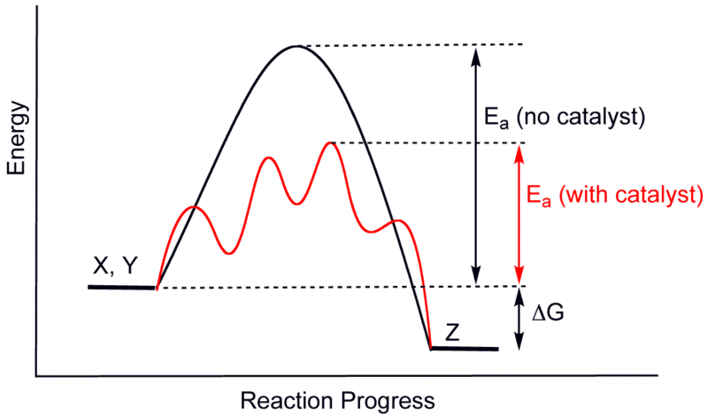
Figure 11: General reaction mechanism of an exothermic reaction (X + Y → Z) with and without catalyst (“Wikimedia Commons, Generic potential energy diagram,” 2008)
Catalysts can be used to facilitate and accelerate chemical reaction mechanisms by reducing the activation energy to avoid this issue (Figure 11).
However, since the Gibbs enthalpy (ΔG) is not changed, the thermodynamics of the overall chemical reactions are also unchanged. The catalyst itself is not consumed during the catalytic process, which comprises various reaction mechanisms. Depending on the aggregation state (its physical state or form—whether it is in a solid, liquid, or gaseous state) of the catalyst and the reacting agents, catalytically supported reaction mechanisms are classified either as homogeneous or heterogeneous catalysis. For the application of catalysts in stoves, heterogeneous catalysis, the reaction of gaseous reactants at a solid catalyst, is essential. The application of honeycomb catalysts or catalytic foamed ceramics, as shown in Figure 12 a) and b), respectively, exemplifies the state-of-the-art use of catalysts in wood stoves (Cork, 2013; VDI 3476 Blatt 1, 2015; Wöhler et al., 2017).
These catalysts include a carrier material (e.g., either ceramic or metallic), an intermediate layer for increasing the geometric surface area of the catalyst, and the catalytic active sites (see Figure 13). The intermediate layer is the wash-coat, made from aluminum oxides (Al2O3), and the active sites are specific combinations of metals; the noble metals platinum (Pt for oxidation of VOC and CO) and palladium (Pd for oxidation of CO) are most often used. For oxidation of NO, Rh can be applied. The specific catalytic reactions take place at the active sites (e.g., oxidation of CO and O2 to CO2).
If the flue gases can reach very high temperatures (600°C–900°C), such as in vicinity of the combustion chamber, non-precious metals, such as nickel (Ni), copper (Cu), and magnesium (Mg), can achieve similar conversion rates (Mack and Hartmann, 2017).
A key indicator for the design of catalysts is the gas velocity (GSV) through the catalysts pore volume. The GSV (gas space velocity) relates to the wet flue gas volume flow (STP), while the volume of the catalyst (Vcat) indicates the mean residence time of flue gases within. Hence, a high GSV is linked to a short residence time of flue gases within the catalytic reactor, and vice versa.
Figure 12a: Honeycomb catalyst with ceramic carrier
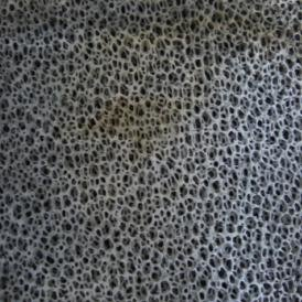
Figure 12b: catalytic foamed ceramic
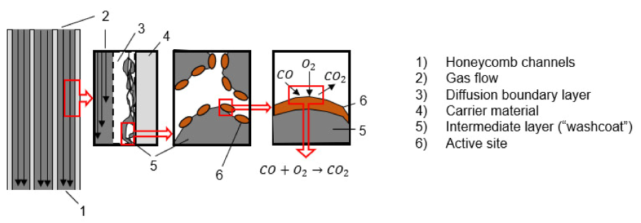
Figure 13: Construction design of a honeycomb catalyst and characteristics of a catalytic reaction (Reichert and Schmidl, 2023a)
Heterogeneous catalytic conversion within honeycomb catalysts can be categorized into seven typical phases, as illustrated in Figure 14 (Wikimedia, 2010):
- Diffusion of reactants (e.g., CO, O2) through the boundary layer (boundary layer diffusion)
- Diffusion of reactants into the pores of the wash-coat (pore diffusion)
- Chemisorption of reactants/educts at the active sites
- Chemical reaction of reactants/educts at the active sites
- Desorption of products from the active sites
- Diffusion of products out of the pores of the wash-coat (pore diffusion)
- Diffusion of products (e.g., CO2) through the boundary layer into the flue gas flow through the honeycomb cells (boundary layer diffusion).
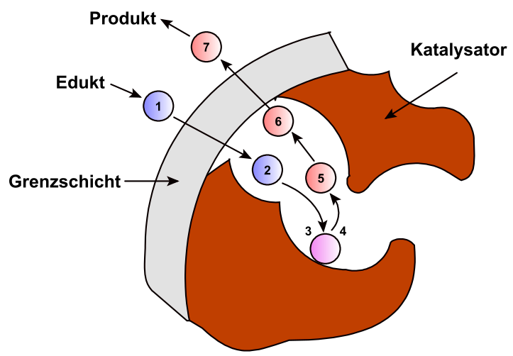
Figure 14: Heterogeneous catalyst
The overall reaction kinetics are influenced by catalytic selectivity, the concentrations of the reactants/products, and temperatures. The limiting effects of catalytic conversion are transport mechanisms, assuming the temperature is sufficiently high, or reaction mechanisms, if temperatures are in the lower limits. For the application of catalysts in stoves, they can either be integrated inside the stove (usually as factory installations) or retrofitted into the chimney, close to the chimney inlet. Relevant design parameters are (Reichert and Schmidl, 2023b)
- Temperatures (minimum, maximum, average);
- Pressure drops;
- By-pass according to requirements of respective European Standards, e.g., 3% of sectional area or at least 20 cm2 of the flown-through sectional area (BLUEFIRE GmbH, 2023);
- Accessibility for cleaning, maintenance, and exchange.
Regarding wood stoves, an overall and local oxygen deficit must be avoided in the flue gas passing the catalyst (which can happen at very high combustion rates, for example) by ensuring good air/flue gas mixture through appropriate design of the combustion chamber and air nozzles.
The reactions that the catalyst promotes are temperature-dependent. When the flue gas temperature exceeds a certain threshold, the catalyst is activated and the exotherm reactions heat it up. This is known as the activation temperature and is usually between 200–300 °C for CO reduction, while reduction of hydrocarbons usually requires higher temperatures (Mack and Hartmann, 2017). When the flue gas is below the activation temperature, the catalyst will not work. Several factors contribute to efficient combustion and ensure a sufficiently high combustion temperature above the activation temperature.
For ceramic catalysts, an overly low temperature is disadvantageous because some oils and tar in the combustion gas will be deposited on the catalyst, which will significantly increase the cleaning frequency of the catalyst. This is why most integrated catalysts are equipped with a bypass supplied with a thermometer or some bi-metallic opening/closing mechanism. At flue gas temperatures lower than the activation temperature, the flue gas must by-pass the catalyst using a manual/automatic valve, while when reaching the activation temperature it passes through the catalyst (White Beam, 2023).
A metal catalyst suffers less from this problem because the high conductivity of the metal structure inside triggers a self-cleaning process that burns the aromatic compounds from tar. Installing a bypass is therefore not necessary, and a manual by-pass option is often sufficient. The upper temperature limit of the catalyst is determined by the structural and chemical limit for the carrier material, the wash-coat and active material, and the production process. The choice of catalyst will therefore determine the operating temperature and catalyst placement. The implementation of a high temperature catalyst at the outlet of the post-combustion chamber is not recommended as tests have indicated unstable reduction efficiencies. The decreasing reduction efficiencies over time are attributed to catalyst deactivation due to blocking of active sites by aerosol condensation. Therefore, the mounting position of the catalyst has to be carefully evaluated in terms of flue gas temperatures in order to minimize risks of aerosol deposition (Mack and Hartmann, 2017).
The aim for all catalyst installations is to ensure fast heating of the catalyst and then to keep it activated through the combustion period assuring that it does not exceed the maximum temperature. In addition, the catalyst must remain easily accessible to the user for removal, cleaning, and replacement. If possible, the location should be chosen so that most of the heat released by the catalyst can still be utilized for heating and does not dissipate in the chimney (White Beam, 2023). A limitation of the ceramic catalyst is the reduction in natural airflow due to high-pressure drops; this can be remedied by increasing the cross-section of the flue gas pipe to reduce the pressure drop while maintaining catalyst efficiency. To further remedy the pressure drop induced by the catalyst, the installation of a flue gas fan may be beneficial (Mack and Hartmann, 2017).
The laboratory tests of Reichert et al. (2018a, 2018b) using five different woodstoves according to EN 13240 (“EN 13240,” 2003) revealed clear emission reduction potential for firewood stoves by integrating ceramic or metallic honeycomb converters (EnviCat® Long Life Plus [EnviCat® VOC, 2023]). Depending on the type of honeycomb catalyst, CO emissions are reduced by 93% (metallic) or 83% (ceramic), OGC emissions by about 30%, and PM emissions by about 20%. The emission limit values for CO, OGC, and PM emissions set during the Ecodesign and Energy labeling process of the European Commission were met by most of the tested catalyst integrated solutions, even when ignition and preheating batch were included. Interestingly, all tested catalysts were integrated in the post-combustion chamber upstream of the flue outlet, with no bypass.
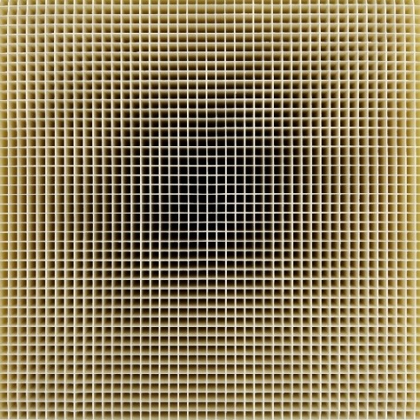
Figure 15: Clariant Catalysts (EnviCat® VOC, 2023)
In a report from “Technologie- und Förderzentrum im Kompetenzzentrum für Nachwachsende Rohstoffe” (TFZ; Mack et al., 2018), clear emission reduction potential is described for integrated catalytic foamed ceramics (active sites: Pt, Pd, Rh). According to experimental tests, the emission conversion efficiencies were 45% for CO, 25% for VOC, and 0% for PM emissions. The conversion efficiencies were evaluated for heating cycles consisting of eight successive batches (batches 1–5 at nominal load with 100% batch mass and batches 6–8 at partial load with 50% batch mass). These tests were performed without any bypass in the flue gas pathway (i.e., bypass closed). The operation of the stove was based on a quick user guide from the user manual. The current tests revealed no CH4 conversion efficiency; this concurs with other studies and is explainable by the average temperature levels in the range of 300–450 °C, which are far too low for catalytic CH4 oxidation (≥ 650 °C; Mack et al., 2018; Reichert et al., 2018b).
Similar results were observed in the measurements by Wöhler et al. (2017), which evaluated an integrated metallic honeycomb catalyst and an integrated catalytic foamed ceramic. During these measurements, the stove was also operated using several batches at nominal (100% batch mass) and partial load (50% batch mass). In contrast to the findings of Mack et al. (2018), PM emission conversion efficiency of about 30% was observed.
For ceramic catalysts tested in the Woodstoves 2020 research project (TFZ, 2020) aiming to develop innovative measures and technologies to further reduce wood combustion emissions, three ceramic catalysts (EnviCat 2520 and two in-house made units) were integrated at different locations in a stove and tested. These tests showed that catalysts fitted to the outlet of the combustion chamber reduced emissions by an average of 70% for CO and 32% for OGC. However, the emission removal efficiencies dropped as the test period (100 hours) progressed to 70% of their initial values. Moreover, cleaning the catalyst was not sufficient to avoid the decline in efficiency; this was due to deactivation by aerosol deposits, mainly as K2SO4 and KCl, which partially blocked the active centers (Mack and Hartmann, 2017).
Emission reductions with metal catalysts in various tests showed a 66% reduction in particulate matter emission (DBFZ, 2018) under lab conditions with an initial concentration of 101 mg/m³. Test results from the SP Technical Research Institute of Sweden revealed a 66% reduction in CO (Rönnback et al., 2016). The test was carried out with a Pd-catalyst covering the whole chimney cross-area, and the duration of the test included four combustion cycles and an average inlet concentration of CO before the catalyst of 3500 ppm. In the same study, a 10%–50% reduction in hydrocarbons was reported in a test including four combustion cycles and 50% according to a short duration test by the DBFZ (DBFZ, 2018).
However, according to the literature (VDI 3476 Blatt 1, 2015) as well as experimental tests (Mack et al., 2018; Reichert et al., 2017), long-term operation will eventually result in agglomerations on the catalyst surface area that reduce the conversion efficiency. Hence, both integrated and retrofitted catalysts must be cleaned and maintained regularly. Some manufacturers recommend only a mechanical cleaning of the catalysts (Brunner et al., 2009), but another possibility is additional cleaning with water, which removes water-soluble agglomerations on the catalyst surface (Reichert et al., 2017).
In addition, different deactivation mechanisms can result in premature losses of conversion efficiencies. Generally, potential deactivation mechanisms of heterogeneous catalysis are classified into three categories (Bartholomew, 2001; Moulijn et al., 2001). Chemical deactivation is caused by selective or non-selective poisoning, which results in a deactivation of active sites by gaseous components (e.g., Pb, Zn, P or SO2). Furthermore, leaching is a type of chemical deactivation caused by undesired chemical reactions between gaseous compounds in the flue gas and the active sites of the catalyst, leading to a loss of those sites. Chemical deactivation mechanisms are mostly irreversible; the operating conditions and the type of catalyst used must therefore be adjusted and critical components (e.g., Pb, P, Zn, and SO2) avoided for Pt- and Pd-based catalysts. Thermal deactivation is caused by the reduction of the surface area of active sites or the porous surface of the wash-coat due to sintering processes. Thermal deactivation is also irreversible and can be avoided by the appropriate design and operation of the appliance. In particular, maximum temperature conditions must be considered for the application of certain catalysts. Mechanical deactivation is caused by fouling processes, namely the deposition of particles on pores and/or active sites, or due to attrition, meaning the loss of active sites due to abrasion or mechanically induced crushing. Both mechanisms lead to a decrease in catalytic conversion efficiency. However, deactivation by fouling is often reversible by cleaning the catalyst or via oxidative regeneration of carbonaceous deposits (Greet et al., 2020).
Financial Considerations
Passive particle filters or catalyst modules cost around €300 or more (Selber machen, Magazine, 2023). Amazon in Germany offers catalytic converter replacements for wood stoves for around €160, which seems to match the starting price of other Europeans suppliers for replacements. The cheapest catalysts are likely produced in China and can probably be bought cheaper than catalysts made in European countries. The ABCAT® Holzrauchfilter retrofit filter costs between €340–€380 (ABCAT®, 2023). Ceramic catalysts are available starting at €700 excluding installation (Chimcat, 2019). At very high temperatures, non-precious metals (e.g., Ni, Cu, and Mg) are also suitable as catalysts. Due to the lower temperature in the case of a chimney retrofit, only precious metals (Pt, Rh, and/or Pd) can be used, which have a lower activation temperature; this may result in higher costs compared to integrated catalysts. (Mack R., et al., 2017).
The Bullerjan (Chimcat type) is offered in Europe, whereas the Firecat (for combustor ACI-68C/ACI-2C) is mainly offered in the United States. Distributors of metal catalysts include Condar (SteelCat type), mainly offered in the United States. The Ecolink (PALCAT and ABCAT type) is mainly available in Europe.
The maintenance and cleaning of a chimney can be more difficult than with standard combustion appliances because the catalyst must be removed during cleaning and in some cases (e.g., ceramic catalysts) is fragile. The catalyst itself is removed manually by the user and cleaned with water or dusted off. Unfortunately, the catalyst does not have a sensor to warn the user that the unit needs to be cleaned. The correct operation of the catalyst thus depends entirely on the common sense of the user.
Ceramic catalysts are susceptible to damage resulting from physical contact, thermal shocks, and obstructions stemming from an incorrectly adjusted bypass or when burning moist wood. Over time, the catalyst honeycomb gradually deteriorates and requires replacement. In contrast, metal catalysts exhibit a slightly greater level of resilience due to their full-metal composition, with the precious metal applied through electroplating. This characteristic renders them more impervious to abrupt temperature fluctuations and aggressive substances, making them less susceptible to damages during cleaning. In a global context, the anticipated operational lifespan of a catalyst under standard usage conditions ranges from five to 10 years. In adverse conditions, such as burning moist or low-quality wood and neglecting proper maintenance, catalyst pores may become obstructed, potentially rendering the unit nonfunctional in as little as a few years or even months. Consequently, it is imperative to exercise additional caution when selecting appropriate fuel and performing regular maintenance.