
MENU
Contents
1. Abbreviations
| Abbreviation | Description |
| ANE | An explosive that is an Ammonium Nitrate Emulsion based blend |
| ANFO | An explosive that is an Ammonium Nitrate/Fuel Oil based blend |
| DKK | Danish kroner (currency) |
| fm3 | Faste kubikkmeter (Norwegian), bank cubic metres (English). The amount rock in situ (in its natural state) in cubic metres before it is blasted |
| HDPE | High-density polyethylene |
| HMX | An acronym for High Melting Explosive (also called octogen), a powerful and relatively insensitive nitroamine high explosive |
| LDPE | Low-density polyethylene |
| lm3 | Løse kubikkmeter (Norwegian), loose cubic metres (English). The amount rock (in its loose state) in cubic metres after it has been blasted and swelled as a result of the space that now exists between its elements |
| NHK | Nordic Working Group for Oceans and Coastal Areas |
| PE | Polyethylene |
| PETN | Pentaerythritol tetranitrate (PETN), also known as penthrite. An explosive material that is structurally very similar to nitroglycerin |
| PP | Polypropylene |
| PVC | Polyvinyl chloride |
| TBM | Tunnel boring machine |
| vct | Water–cement ratio. The ratio of the weight of water to the weight of cement used in a concrete mix |
2. Introduction
In recent years there has been an increasing awareness of plastics entering the sea from blasted rock. There is a need for further knowledge and information about this and which type of prevention and measures that can be taken to stop the plastics from entering the sea or stop the spreading of plastics that already have entered the sea.
This report describes how plastics originating from placement of rock masses from tunnelling and other blasting activities can be prevented from entering the sea. During tunnel construction plastics are used in many different components such as explosives, lead wires (including shock tubes) and detonators as well as in fibrous reinforcement (including macrofibres and microfibres) of shotcrete linings in tunnels.
By implementing relatively simple measures, it is estimated that a minimum 75% reduction of spreading of plastics to the sea from tunnelling and blasting compared to today’s situation should be possible.
The report is divided into the following main parts:
- The difference between constructing tunnels by using blasting and excavation of blasted rock or by full-face boring using a TBM (Tunnel Boring Machine) (Chapter 3).
- An overview of sources of plastics from tunnelling and other blasting activities (Chapter 4).
- Estimates of the amount of plastics that can enter the sea from tunnelling and other blasting activities (Chapter 5).
- How can we avoid plastics from tunnelling and other blasting activities reaching the sea (Chapter 6).
- How can we stop spreading plastics from blasted rock that has been placed in the sea (Chapter 7).
- How can we monitor plastic emissions from tunnelling and disposal of blasted rock (Chapter 8).
- How can we replace plastics used in tunnelling and other blasting activities with other products, including plastics with less risk of emissions (Chapter 9).
- A case study from the Faroe Islands from two ongoing tunnelling projects where plastics in the sea due to placement of rock masses is an issue (Chapter 10).
- Summary and recommendations on how to avoid polluting the sea with plastics from tunnelling activities (blasting and shotcrete) (Chapter 11).
The main target audiences for the report are road authorities, environmental authorities, contractors and consultants that work with tunnelling and other blasting activities.
The project has been funded by the Nordic Working Group for Oceans and Coastal Areas (NHK) which is affiliated to the Nordic Council of Ministers. The mandate of the Nordic Working Group for Oceans and Coastal Areas (NHK) is to support the Nordic countries in activities that help collate data and establish the scientific basis for Nordic initiatives to combat pollution in the marine and coastal environments.
Participants:
- Veera Komulainen, Environmental Manager, Oy Forcit Ab, Finland (All workshops and report).
- Marion Børresen, Senior Adviser Environment, NGI, Norway (All workshops and report).
- Pär Elander, Senior Consultant Environment, Elander Miljöteknik AB, Sweden (All workshops and report).
- Jens Laugesen, Chief Specialist Environment, DNV GL AS, Norway (Project manager, all workshops and report).
- Hans Peter Arp, NGI, Norway, Senior Specialist Environment, NGI, Norway and Adjunct Full Professor, NTNU (Workshop 1 and report).
- Teitur Samuelsen, Director at Eystur- og Sandoyartunlar, The Faroe Islands (Workshop 3 and report).
- Einar Brimnes, Project Manager at Eystur- og Sandoyartunlar, The Faroe Islands (Workshop 3 and report).
Acknowledgements:
We would also thank all the persons that have helped us with input to this report, especially:
Merete Landsgård, Statens vegvesen (Norway)
Bente Breyholtz, Norconsult
Olaf Rømcke, Orica Norway AS
Disclaimer: Information to this report has been gathered from many sources. Sometimes the information varies concerning for example products and amount of plastics. The authors have tried to evaluate and present the data as correct as possible and have given references to the data.
3. Tunneling versus full-face boring (TBM)
Tunnels can be constructed using blasting and excavation of blasted rock (Figure 3) or by full-face boring using a TBM (Tunnel Boring Machine) (Figure 1).
In the Nordic countries blasting of tunnels is the dominating technique, probably because TBM has been considered to be a more expensive technique from which we have less experience, while blasting is a well-known technique from which we have long experience. Another contributing factor is probably the longer time needed from planning to the start of tunnel construction and that more thorough investigations are needed in planning for full-face boring with a TBM.

Figure 1
Top: Tunnel boring machine used in the Follo Line Project, Norway. Picture: Cato Mørk/GJV.
Bottom: Rectangular tunnel boring machine (TBM). Picture: China Railway Engineering Group (CREG), 2016.
However, today it is questionable whether TBM generally is the costlier method, especially for longer tunnels where the initiating costs have less impact. Furthermore, from a sustainability perspective full-face boring is the favourable method with regard to impact of water quality, energy consumption and use of resources. A drawback though, is that the detached rock from a TBM has a lower quality (is relatively fine and sharp-edged) and is difficult to use as a construction material (Goméz-Bergström and Bahr, 2015). The detached rock from a TBM is not suitable for sea disposal. With the TBM technology we have today, it is possible to replace conventional blasting by using a TBM for many tunnelling projects, if the geology is suitable. TBMs are in general circular, which is very suitable for railways, sewage tunnels etc. For road tunnels TBMs are not always ideal as almost the double cross-section is excavated compared to what is needed for the road. In recent years there also has been developed TBMs for other types of cross-sections, like for example rectangular TBMs (Figure 1). Using TBMs for subsea tunnels can involve special challenges with handling water seepage while drilling. This can be solved by using a slurry pressure balanced TBM, specifically designed to counterbalance the water pressure at the face.
4. Overview of sources of plastics from tunnelling and other blasting activities
4.1 Plastics - sources
Plastics from blasting activities can originate either from above ground activities (Figure 2) or from underground activities like tunnelling (Figure 3).
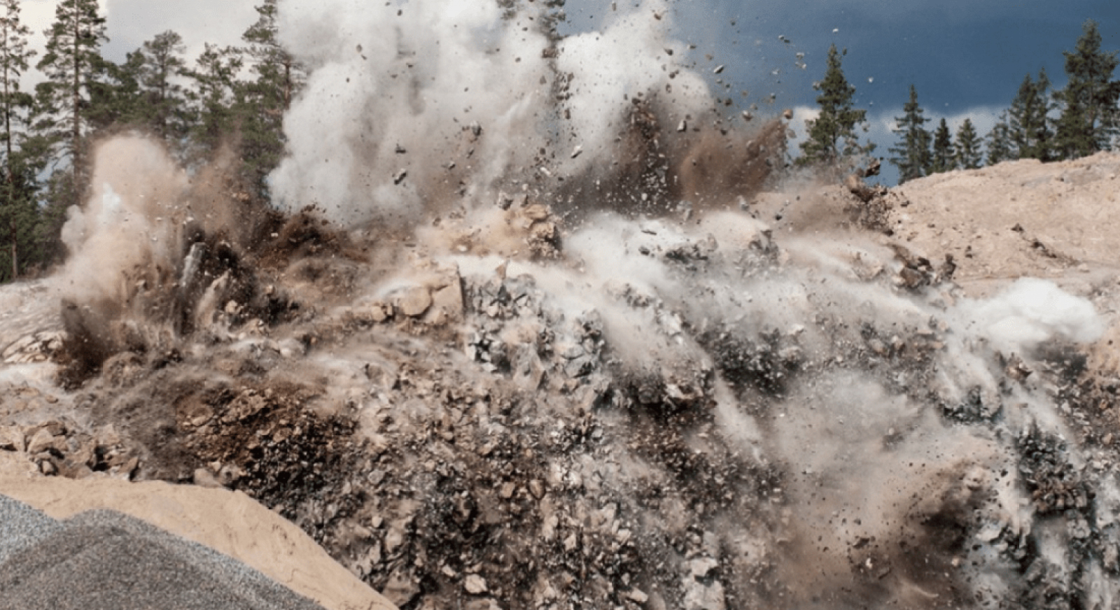
Figure 2
Above ground blasting. Picture from https://www.berglaget.se

Figure 3
Tunnelling with blasting technique. Drilling holes for placement of explosives in a tunnel project in Stockholm, Sweden. Picture: Mikael Ullén, from https://arstechnica.com/
4.2 Plastics from blasting
Blasting is the controlled use of explosives to break rock for excavation of for example tunnels.
A blasting operation has the following main operations:
- Drilling holes for the explosives.
- After all the drill holes are drilled, the entire rock surface of the tunnel is charged by placing the explosives and mounting the detonators and lead wires. The explosives are normally injected into the drill holes as a jelly-like emulsion (Figure 4); today more than 99% of the explosives used in tunnels are emulsions. The alternative is to use explosives in cartridges which are inserted one at a time into the drill holes and charged, but this a method that is rarely used in Nordic tunnelling.
- The explosives are timed to detonate based on a precise calculation.
- After the explosion the blasted rock (rock cut) is collected and transported out of the tunnel and placed on land or in the sea.
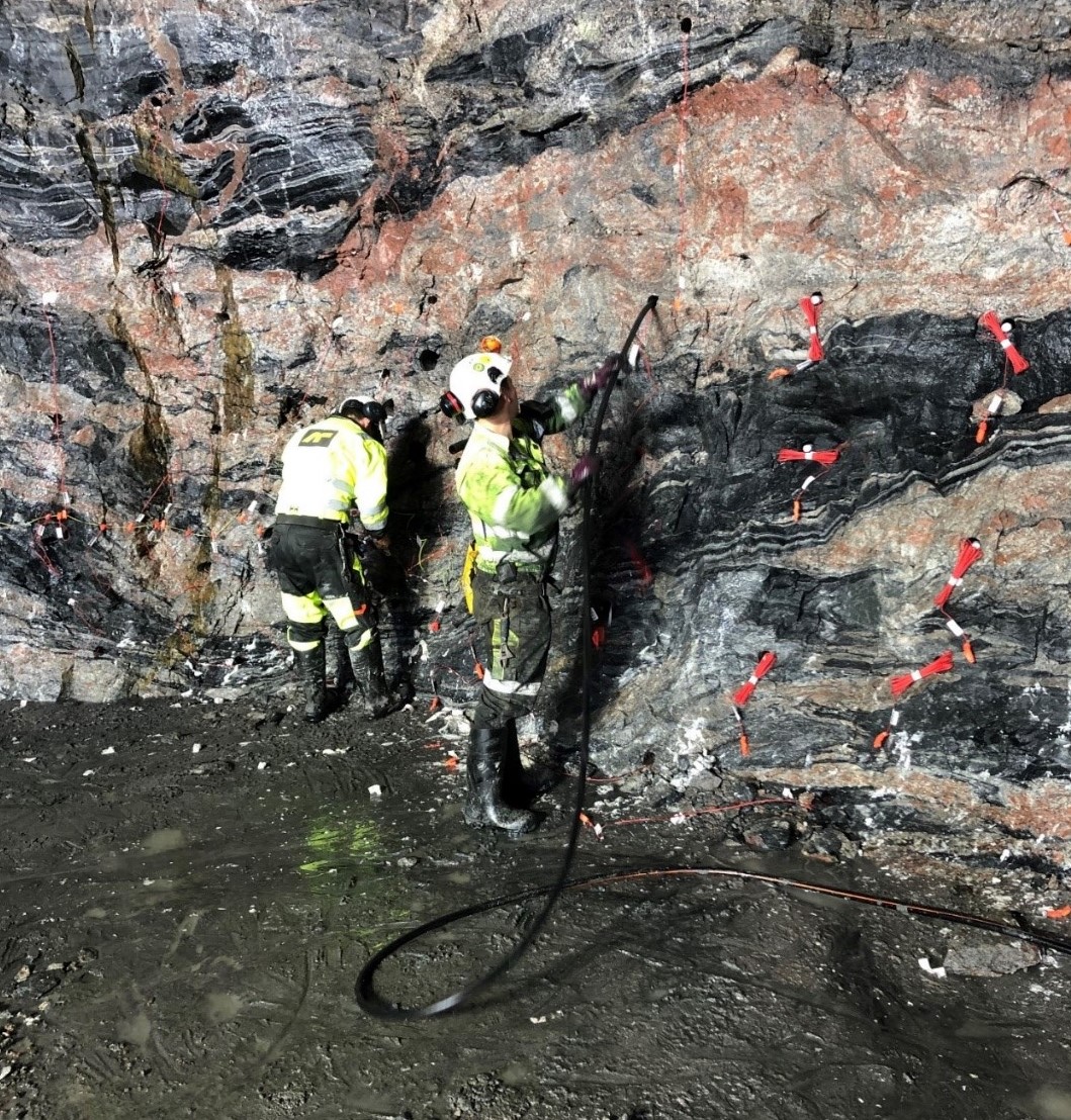
Figure 4
Injection of explosives and placement of detonators (not visible) and lead wires (red). Picture from Orica Norway AS.
A large variety of explosives and detonators are used for blasting. Higher velocity explosives are used for relatively hard rock in order to shatter and break the rock, while low velocity explosives are used in soft rocks to generate more gas pressure and provide a greater heaving effect. For a long time ANFO based blends (ammonium nitrate/fuel oil) were commonly used in tunnelling due to lower cost than dynamite. The most common blend today is emulsion explosives (also called ammonium nitrate emulsions, ANE). They are a mixture of ammonium nitrate and gas components. In the Nordic countries about 80% of the explosives used today for blasting are ANE. The components are transported in trucks and sensitised into an explosive when pumped in the borehole at the site.
Plastics have been used in blasting operations for a long time and they can be found in many of the components that are used for blasting operations (chapter 4.3).
4.3 Components used for blasting and type of plastic they contain
Many of the components used today for blasting contain plastic components. Here an overview of the types of plastic that blasting components can contain is provided. The components are divided into explosives, detonators, lead wires, fuses and other components such as plugs, casings, connectors and delay blocks.
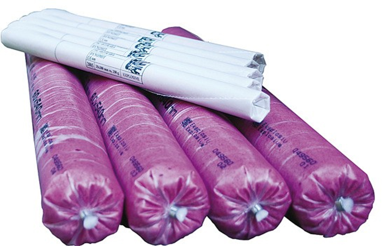
Figure 4.1
Component: Explosives: (with plastic cartridge).
Description: Dynamite with plastic cartridge. Picture from https://www.vegvesen.no
Type of plastic that the component contains: Not reported. Presumably PVC, PE or similar. Should normally be destroyed from the detonation.
Figure 4.2
Component: Explosives: (emulsion pumped into the drilling hole).
Description: A sample of explosive emulsion in a cup. Picture from Orica Norway AS.
Type of plastic that the component contains: None.

Figure 4.3
Component: Detonators (blasting caps): Electric detonators. Non-electric detonators. Electronic (digital) detonators.
Description: See figure.
Type of plastic that the component contains: Electric detonators, non-electric detonators and electronic (digital) detonators all contain some plastic. There will typically be some grams of plastic (presumably PE) in each detonator.
Figure 4.4
Component: Detonators (blasting caps): Electronic wireless detonators.
Description: An electronic wireless detonator. Picture from Orica Norway AS. Electronic wireless detonators are quite new on the market. The big advantage is that no lead wires (also known as blasting wires) are needed. The detonation is obtained by a radio transmitter that sends a signal directly to the detonator. Electronic wireless detonators are still far more expensive than other detonators that need some type of lead wire. Therefore they are still in little use, and thus far have been mainly used in the mining sector. They have been tested for tunnelling but not used in any full-scale project.
Type of plastic that the component contains: The whole shell of the detonator is made of plastic (no information on which type of plastic). The detonator should be destroyed from the detonation.
Figure 4.5
Component: Lead wires (incl. shock tubes and blasting wires): Shock tubes.
Description: A shock tube detonator with a blasting cap. Picture from www.dsadetection.com. Lead wires are the wires that are connecting the (electrical) power source with blasting caps that detonate the explosives. (They are sometimes also called firing cables).
A shock tube is a small-diameter hollow plastic tubing used to transport an initiating signal to an explosive charge. It contains a smaller quantity of high explosive compared to a detonating cord. The most common product is with 3 mm outer diameter and 1 mm inner diameter, with a tiny dusting of HMX/ aluminium explosive powder on the tubing's inner surface. It detonates at a speed greater than 2000 m/s.
Type of plastic that the component contains: The Nonel Dyno® Line® shock tube detonator has polyethylene (PE) in the middle and outer layer and polyvinyl chloride (PVC) in the sleeve, total amount of plastic is about 5 g/m. Observations after blasting with shock tube detonators indicates that the plastic does not get destroyed from the blast (or only to a very limited extent).
Figure 4.6
Component: Lead wires (incl. shock tubes and blasting wires): Blasting wires for electronic detonators.
Description: A blasting wire with a blasting cap. Picture from Orica catalogue. Blasting wires are used in tunnels but not as much as shock tubes. There has been a slow increase in use in the Nordic countries in the last couple of years.
Type of plastic that the component contains: The blasting wire eDevTM II (from Orica) has a coating of polypropylene.
Figure 4.7
Component: Lead wires (incl. shock tubes and blasting wires): Blasting wires for electric detonators.
Description: Blasting wires. Picture from www.eocable.com. Blasting wires are still used a lot but not in tunnels in the Nordic countries. Most are made of copper that is insulated with plastic.
Type of plastic that the component contains: The blasting wires on the picture are made of 0.75mm2 PVC insulated copper cables.
Figure 4.8
Component: Fuses: Detonating cords.
Description: Detonating cord. The illustration to the left is from Orica and the picture to the right is from https://www.dsadetection.com. Detonating cords are flexible plastic-coated cords usually filled with pentaerythritol tetranitrate (PETN, penthrite), mostly about 5–100 g/m. With PETN the velocity of the detonation is approximately 7000 m/s, and any common length of detonation cord appears to explode instantaneously. In tunnelling the detonating cords (typically with 5 and 10 g/m of penthrite) are used to initiate the shock tubes.
Type of plastic that the component contains: A detonating cord contains a thread of polypropylene or cotton and is coated either with PVC or PE (thermoplastic) (ref. Forcit products). There is no data on the amount of plastics in detonating cords but probably some grams per metre. The cord will be completely destroyed when it is used because it burns.
Figure 4.9
Component: Stemming plugs.
Description: Stemming plugs. Pictures from www.oresomeproducts.com/hole-plugs/ and from https://www.blasterstool.com. Stemming plugs are used to prevent the loss of explosives energy from blowouts by plugging the end of the drill hole. Stemming plugs are only used together with cartridges and not with slurries, and in practice not commonly used in Nordic tunnel construction.
Type of plastic that the component contains: Stemming plugs are made of plastic, typically LDPE, and are produced in a lot of different sizes.
Figure 4.10
Component: Borehole plugs.
Description: Borehole plugs. Pictures from https://boreholeplugs.com. Borehole plugs are used to mark the drill holes. Borehole plugs are only used in surface blasting. Borehole plugs are placed to prevent loose material from falling into the hole. Borehole plugs are normally removed before blasting and reused.
Type of plastic that the component contains: Borehole plugs are made of plastic, typically LDPE, and are produced in a lot of different sizes.
Figure 4.11
Component: Blasthole casings.
Description: Blasthole casings. Pictures from Bente Breyholtz (top) and Orica catalogue (bottom). Blasthole casings are used in tunnels to protect the drilling hole from water intrusion. Water intrusion could lead to that the slurry emulsion (ANE) is washed out. Typical length of a blasthole casing is slightly less than the borehole length (4–5 m).
Type of plastic that the component contains: The blasthole casings should be removed before blasting, but that is not always the case. They can be reused until they are too worn for further reuse. Blasthole casings that are not removed before blasting will not be fully destroyed during the explosion and normally plastic is found in the blasted rock (rock cut) after the explosion. There is no information on the type of plastic, it could be HDPE or similar.
Figure 4.12
Component: Plastic connectors.
Description: Plastic connectors. Picture from https://explosives.net/product/mini-detcord-clip/. Plastic connectors are plastic clips that are used for connecting detonation cords or connecting detonating cords and shock tubes.
Type of plastic that the component contains: Plastic connectors are typically made of PVC. The weight will vary between different models and producers.
Figure 4.13
Component: Surface delay blocks (only for shock tubes).
Description: Surface delay block (blue). Picture from http://online.blasttraining.com.au. Surface delay blocks are used for advanced sequencing of non-electric blasts for open cut operations. Surface delay blocks are made of a low energy detonator housed in a plastic block. The surface delay block enables a number of shock tubes to be clipped in. The surface delay blocks are only used for special purposes in tunnels.
Type of plastic that the component contains: Surface delay blocks are made of plastic, probably PE. The surface delay blocks will not be destroyed during the explosion.
Figure 4.14
Component: Connecting sleeves.
Description: Connecting sleeves (red part shown on the picture). Picture from Bente Breyholtz. Connecting sleeves are an extra protection of exposed areas of the shock tube (5–10 cm) where it is connected to the blasting cap.
Type of plastic that the component contains: Connecting sleeves are made of soft plastic (type not known). There are indications that remnants of plastic from connecting sleeves have been found in the sea after tunnel blasting in Norway.
4.4 Plastics from shotcrete
Shotcrete is a mixture of aggregate (normally sand), portland cement and water used in tunnel construction to bind the walls of the tunnel to prevent leaks and fragmentation. The shotcrete is normally placed as soon as possible after the blasted rock has been removed. The wet shotcrete is sprayed in place by the nozzle of a spray gun that uses compressed air (Figure 5).
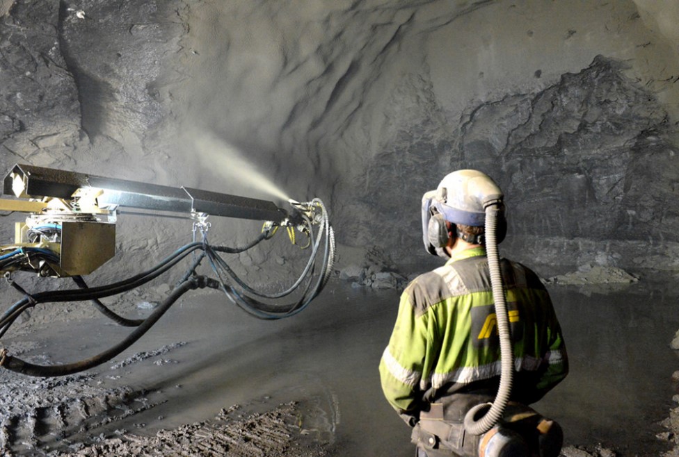
Figure 5
Application of shotcrete. Picture: Bente Breyholtz.
For structural uses, shotcrete is usually applied over a framework of reinforcing bars and steel mesh. To increase the strength of the shotcrete reinforcement is added in the form of macro and/or microfibres made of plastic. The fibres also serve as fire protection to prevent chipping of the shotcrete.
Macro-synthetic fibres (macrofibres) are typically made of polyethylene/polypropylene (density=0.9 g/m3) or nylon (density=1.1 g/cm3), with a thickness of ≥ 300 µm and a length of ≥ 38 mm (Figure 6).
For structural uses normally about 6 kg of macrofibres/m3 shotcrete is applied.
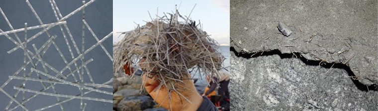
Figure 6
Macro-synthetic fibres. Pictures from: http://www.concrete.org.uk/fingertips-nuggets.asp?cmd=display&id=842# (left) and https://naturvernforbundet.no/ (middle) and Bente Breyholtz (right) (shotcrete with macro-synthetic fibres).
Micro-synthetic fibres (microfibres) are typically made of the same materials as the macro-synthetic fibres (polyethylene/polypropylene or nylon) and with the same densities. The thickness of the fibres is 18 – 64 µm and they have a typical length of 6 – 64 mm (Figure 7).
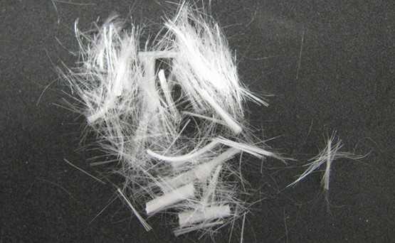
Figure 7
Micro-synthetic fibres. Picture from: https://www.contecfiber.com/en/products/fibrofor-multi/
Microfibres are mainly used as fire protection and macrofibres as reinforcement of the shotcrete.
For fire protection normally about 2–3 kg (sometimes up to 4 kg) of microfibres/m3 shotcrete is used (Svenska Betongföreningen, 2011).
4.5 Other sources
There are also other sources of plastics in tunnelling, in addition to what is used for blasting and shotcrete:
- Foam: Injection of polyurethane foam is used for plugging water leakages in tunnels (Figure 8).
- Packaging: Different type of plastics are used as packaging material to protect and preserve products used in the tunnel construction (Figure 9).
- Rock bolts: Rock bolts made of polyester to secure loose rock is used frequently in tunnels (Figure 10).
- Styrofoam blocks: Styrofoam lightweight blocks can be used for insulating or sealing off tunnels (Figure 11).
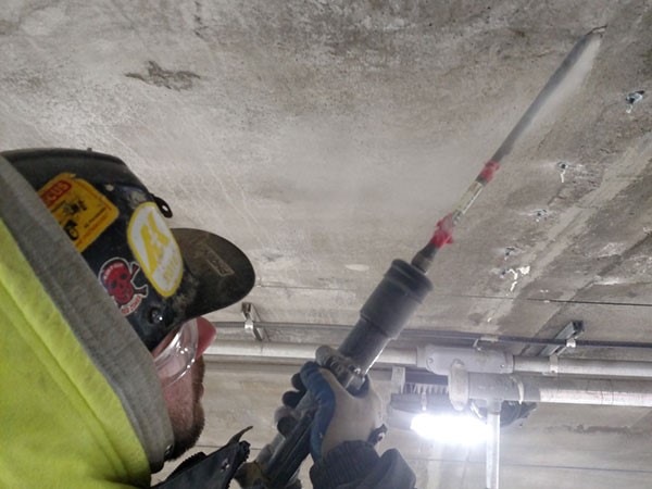
Figure 8
Polyurethane foam is injected behind a tunnel liner. Picture from: http://themicongroup.com/tunneling/
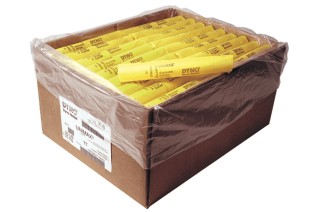
Figure 9
Explosives (dynamite) packed in cardboard box and protected with plastic. Picture: https://tripwireops.org
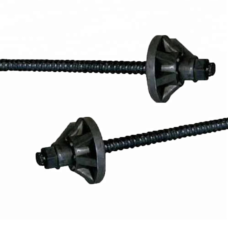
Figure 10
Fibre glass reinforced polyester rock bolts. Picture from: https://www.alibaba.com
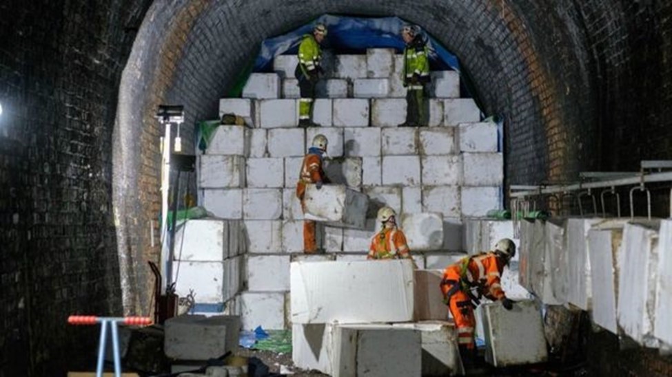
Figure 11
A degrading tunnel close to Dunfermline in the United Kingdom is filled with polystyrene to secure the tunnel. Picture: Tony Marsh, from https://www.bbc.com/news/uk-scotland-edinburgh-east-fife-43824142
These sources will not be dealt with further in the report. The report will concentrate on plastics originating from blasting (explosives, detonators etc.) and from shotcrete (reinforcement, fire protection).
5. Amount of plastics that can enter the sea from tunnelling and other blasting activities
In this chapter we present estimates on the amount of plastics that can enter the sea from tunnelling and other blasting activities.
5.1 Plastics generated worldwide and in Europe
The amount of plastics generated worldwide and in Europe every year is very high. There are no exact numbers but the worldwide production of plastics in 2018 almost reached 360 million tonnes. In Europe, plastics production almost reached 62 million tonnes in 2018 (PlasticsEurope, 2019).
Worldwide it is estimated that about 2 billion people are living within 50 km of a coastline and that they will cause about 8 million tonnes of plastic to spread to the oceans every year (Figure 12).
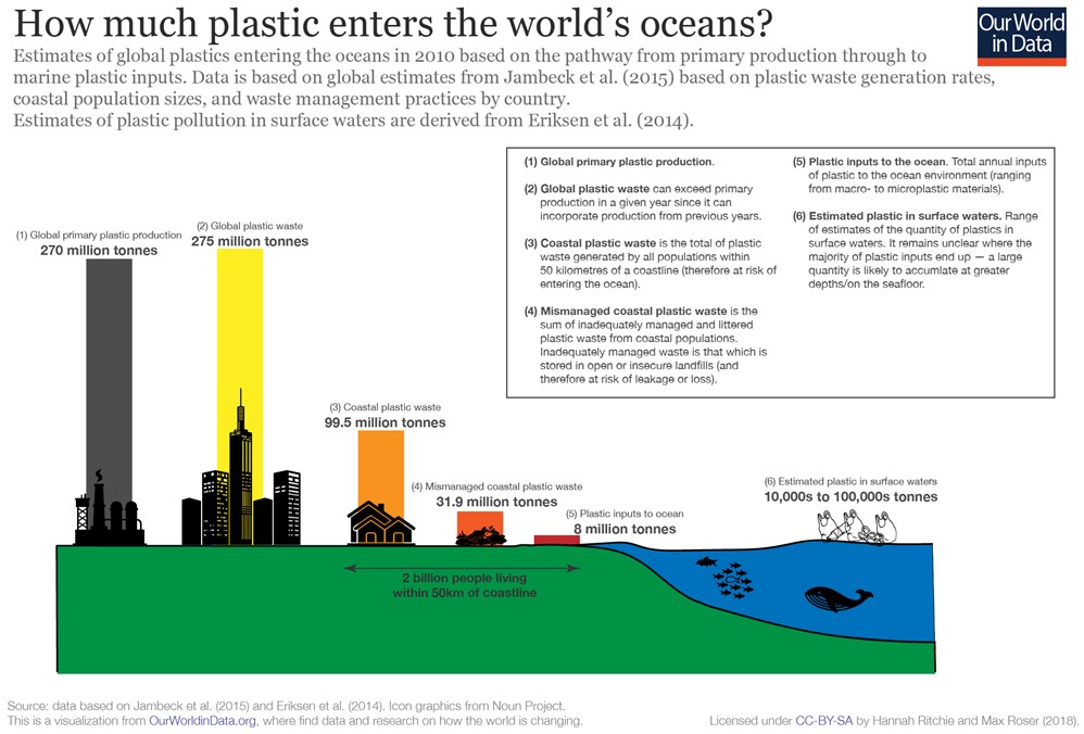
Figure 12
Plastic entering the world’s oceans. From: https://ourworldindata.org/plastic-pollution
Globally for the whole building and construction sector about 13 million tonnes of plastic is generated yearly (Figure 13). There exists no specific data for how much of the 13 million tonnes that is related to plastics used in rock blasting and in shotcrete reinforcement.
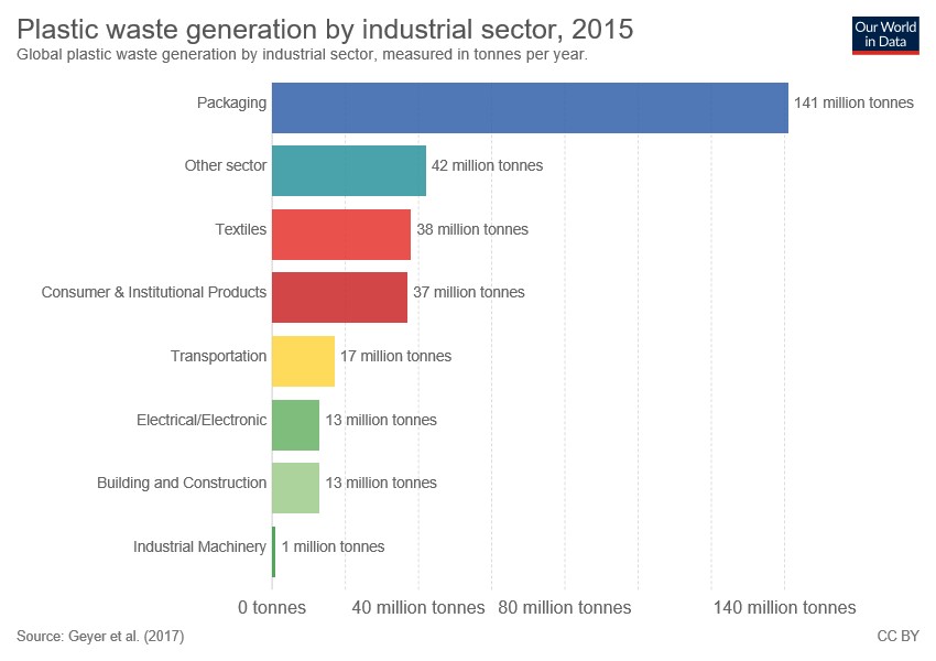
Figure 13
Plastic waste generation worldwide by industrial sector. From: https://ourworldindata.org/plastic-pollution
Most of the plastic waste going to the oceans ends up on the seabed (94%) and only 1% is floating. The remaining 5% of the plastic waste ends up on the shores (Figure 14).
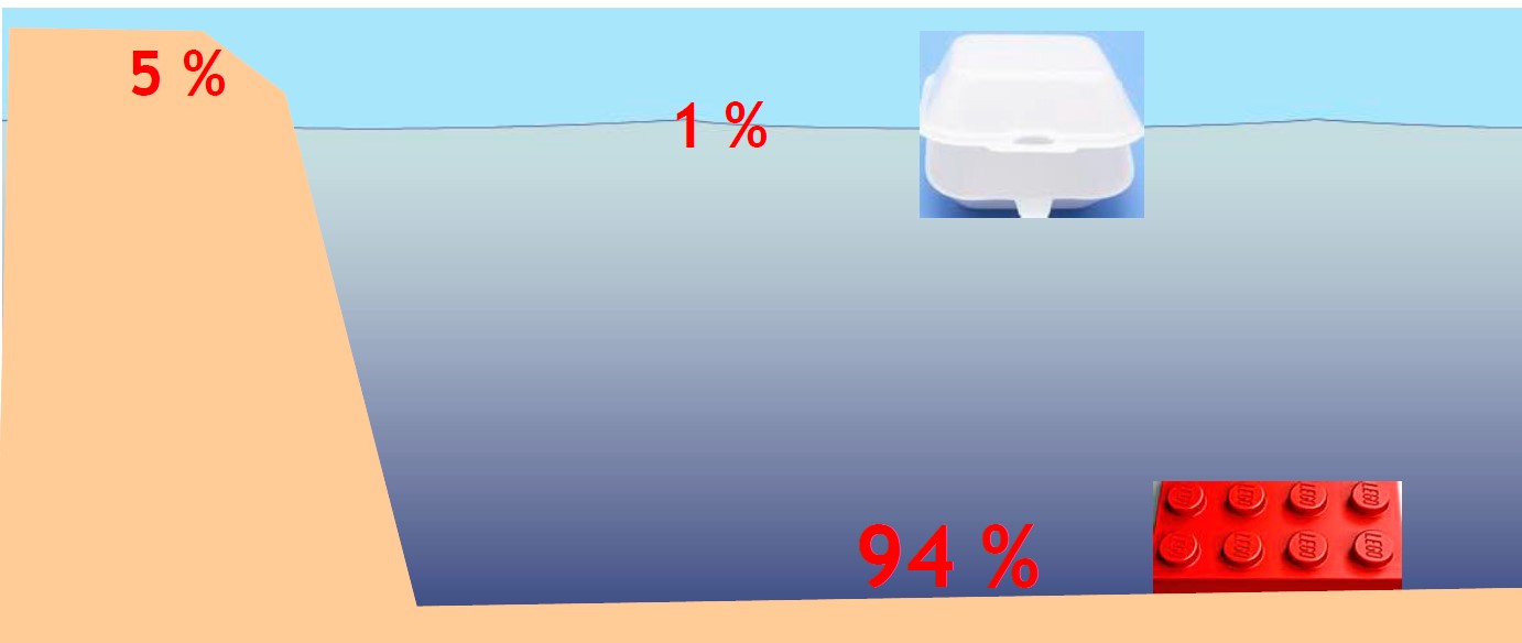
Figure 14
Plastic waste going to the sea ends mainly up on the seabed. From: Hildonen (2019).
5.2 Plastics generated from tunnelling and blasting activities
There are very little statistics on the amount of plastics used in tunnelling and blasting activities, and subsequently how much that ends up in the seas. Here we conduct an estimate of sea emissions for Norway of plastic fibres from shotcrete (Figure 15) and plastics from blasting. The estimate is based on the assumption that the tunnelling and blasting activities are relatively close to the sea and that the plastics generated by the activities can end up in the sea (i.e. no landfill).
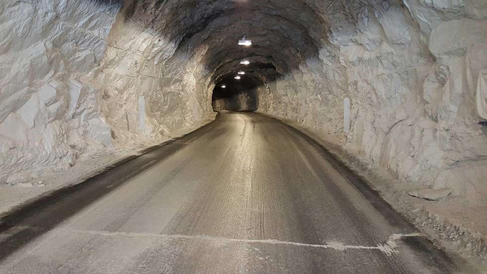
Figure 15
The Breitind tunnel in Mefjorden, Norway is an example where shotcrete has been used. A special type shotcrete has helped to make this tunnel brighter. Picture: www.folkebladet.no/nyheter/article11214413.ece
The calculations are based on several references: Breyholtz (2017), NFF (2018), Hildonen (2019), and Statens vegvesen (2019 and 2020).
| Calculation of plastic fibres from shotcrete |
| Basic assumption: 60,000 m (60 km) of tunnels are built every year in Norway that are treated with shotcrete |
| Typical area of the ceiling and walls of a road tunnel: 30 m2/m tunnel |
| Total area of ceilings and walls in the tunnels: 1,800,000 m2 (60,000 m x 30 m2/m) |
| Average thickness of the shotcrete that is placed: 0.04 m |
| Amount of shotcrete that is placed: 72,000 m3 (0.04 m x 1,800,000 m2) |
| Amount of plastic fibres in the shotcrete: 6 kg/m3 fibres |
| Total amount plastic fibres used per year in the tunnels: 432,000 kg |
| Assuming there is 10% spill of shotcrete with plastic fibres |
| There is a yearly potential for 43,000 kg spill of plastic fibres from shotcrete in tunnels that could go to the sea. |
| Calculation of plastics from blasting |
| Basic assumption: 60,000 m (60 km) of tunnels are built every year in Norway with blasting technique |
| For every blast typically 150 holes with a length of 5 m are drilled: a total of 750 m with drilling holes |
| Totally 12,000 rounds are blasted (60,000 m/ 5 m) where the drilling holes are loaded with detonator and explosives |
| A typical tunnel cross section is 75 m2 (Profile T10.5) |
| This generates approximately 7 million m3 of blasted loose rock per year (60,000 x 75 x 1.6). 1.6 is the expansion factor from the solid in situ m3 to the m3 of loose blasted rock. |
| Shock tubes with detonators |
| Shock tubes with detonators (Nonel) are mostly used for tunnelling in Norway. They contain 5 grams of plastic per metre. It is assumed that the plastic does not get destroyed from the blast (see chapter 4.3). |
| For every drilling hole approximately 7.8 m of shock tube is used, that means 39 g of plastic for every hole (7.8 m x 5 g/m) or 5,850 g for each blast (150 holes x 5 g/m x 7.8 m) |
| This generates approximately 70,000 kg of plastics from the shock tubes (12,000 blasts x 5.85 kg/blast) |
| Blasting wires with electronic detonators |
| Blasting wires with electronic detonators is another alternative, but less used than shock tubes with detonators. |
| Estimates done by Statens vegvesen show that for blasting wires with electronic detonators, the total amount of plastics would be between 19,000 to 47,000 kg, if such a system would have been used instead (Figure 16). The relatively large variation is due to that there are different producers with different products. In this estimate the plastic connectors are included, they are 44 to 54% of the total amount of plastic. |
| In addition, there could be some plastic from other outfit like blasthole casings. |
| There is a yearly potential for 70,000 kg spill of plastics from blasting in tunnels that could go to the sea. The calculation is based on the assumption that shock tubes with detonators are used. |
The calculated estimates show that plastics used in tunnelling can contribute to substantial spills to the sea from plastic fibres in shotcrete (43 tonnes per year in Norway) and from blasting (70 tonnes per year in Norway).
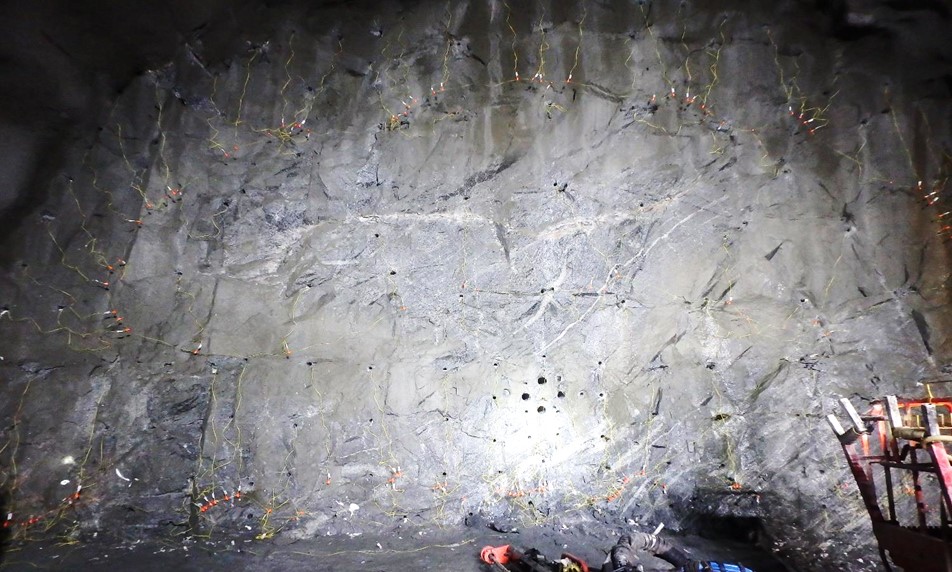
Figure 16
The tunnel that was used for calculating the example with blasting wires and electronic detonators. Picture: Bente Breyholtz.
6. Measures to avoid plastics from tunnelling and other blasting activities reaching the sea
In this chapter we describe how we can avoid plastics from tunnelling and other blasting activities reaching the sea. In the following chapter we will describe how we can prevent spreading of plastics from blasted rock that has been placed in the sea.
6.1 Avoiding spreading plastics from shotcrete in the tunnel
In the Nordic countries shotcrete is reinforced with macrofibres made of plastic or steel. According to figures presented by Hildonen (2019) plastic fibres used as reinforcement in shotcrete can constitute 75% of the discharge of plastics from blasted rock dumped in the sea. This is mainly a consequence of that when applying shotcrete in a tunnel, there will be a rebound loss and some of the shotcrete will fall onto the tunnel floor. Rebound loss is the part of the shotcrete that does not adhere to the surface during application. The rebound loss is normally less than 5% (Statens vegvesen, 2012) but can be up to 10% (Breyholtz, 2018). The density of plastic fibres is normally about 0.9 g/cm3, and thus they float in water. The steel fibres are heavier (7.8 g/cm3) and will not float.
There are several ways that the plastic and steel fibres from the shotcrete can be spread during the construction of the tunnel:
- Plastic and steel fibres from the rebound loss of the sprayed shotcrete will end up on the tunnel floor. Research shows that the majority of the fibres from the rebound loss will be bound to the shotcrete (Statens vegvesen, 2012). If the rebound loss is not collected the fibres can spread to the sea.
- Plastic fibres and other plastic waste float with the tunnelling water and will accumulate in the ditches within the tunnel (Statens vegvesen, 2012).
- Plastic fibres and other plastic waste float with the tunnelling water out of the tunnel and will accumulate in the water cleaning facilities outside the tunnel or continue further into the closest recipient.
The application of the shotcrete will cause some of the microfibres (for fire protection) to be swirled up in the air. These fibres are a very fine particulate matter and pose a problem for the working environment and machinery in the tunnel. The extent to which plastic fibres can be absorbed by or damage aquatic organisms is an unanswered question.
There are several ways to avoid spreading of plastic fibres with effluent, these are organized as applying to just macrofibres, just microfibres, or both:
Macrofibres:
- Replace the plastic fibres by steel fibres or plastic fibres with higher density than water (e.g. nylon, note this only applies for macrofibres as microfibres behave pseudo-colloidally in water regardless of density).
- If the blasted rock has plastic macrofibres made of polyethylene or other low-density plastics it can be treated in a water bath to separate loose free macrofibres (which float). Such a treatment can be costly and hard to carry out because of high capacity requirements.
Microfibres:
- The use of a water spray barrier to stop spreading airborne fibres during application of shotcrete (Figure 17).
- An untested solution would be to install a suction fan close to the shotcrete rig which catches airborne fibres and dust.
Both macrofibres and microfibres:
- Improving the shotcrete techniques and thereby decreasing the loss will have a positive impact on the fibre release onto the tunnel floor.
- Remove all the remaining blasted rock on the tunnel floor before the shotcrete is applied. Then the rebound from the shotcrete does not get mixed with blasted rock, and uncontrolled spreading of fibres can be reduced.
- Actively collect the rebound loss of shotcrete (and fibres) from the tunnel floor and dispose it safely.
- Install water cleaning facilities for the effluent water from the tunnel. Remove plastic fibres from the filters in the water cleaning facilities.
- Landfilling the blasted rock in such a way that fibres cannot be spread from the landfill.
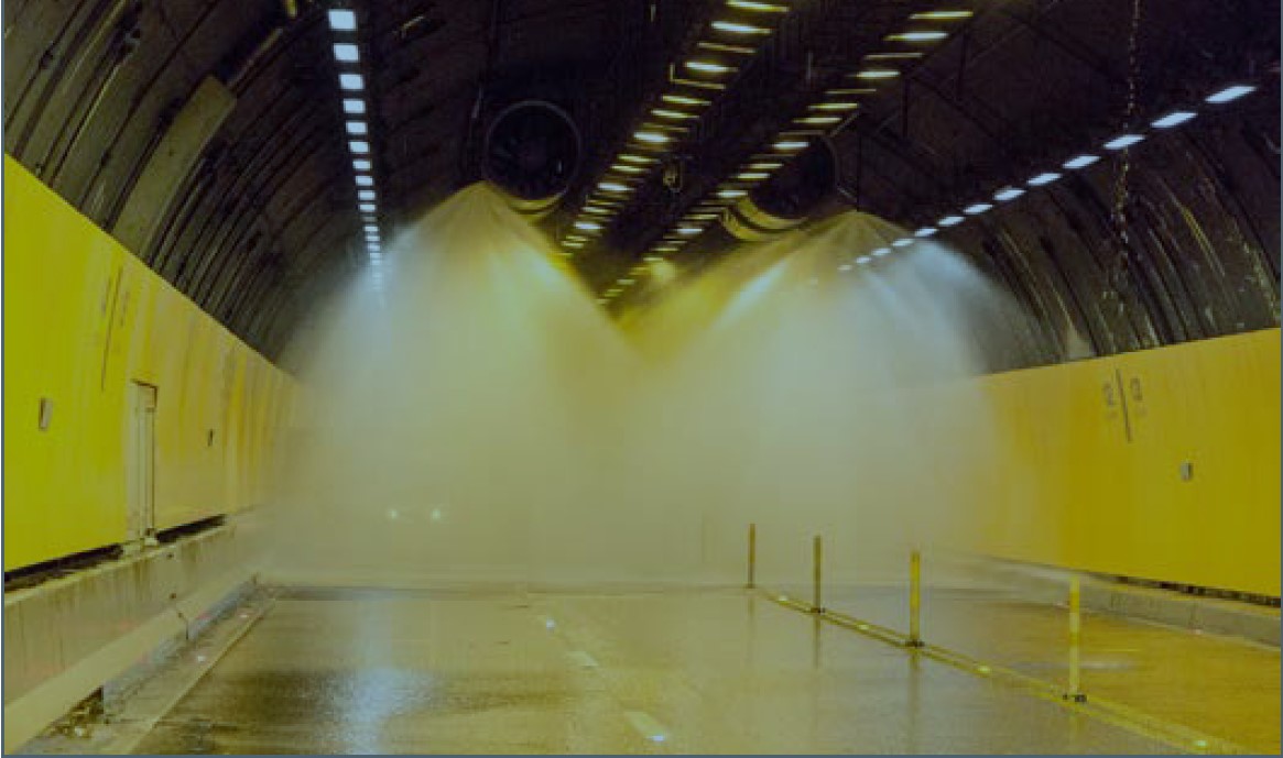
Figure 17
Water spray barrier. This specific barrier is to stop spreading of fire in a tunnel, but such a barrier can also be used to stop spreading airborne fibres. Picture from: https://international.fhwa.dot.gov/pubs/pl18030/fhwa_pl18030.pdf
6.2 Avoiding spreading plastics from blasted rock in the tunnel
After the blast the blasted rock is on the tunnel floor waiting to be transported out of the tunnel. This is also a point where there can be substantial water intrusion because the leaking points have not been grouted yet. Further the blasted rock on the tunnel floor is often watered with a water cannon to reduce the dust after the blast. The effluent water from water intrusion and the water cannon can spread the plastic that is in the blasted rock on the tunnel floor.
To avoid this, it is important to reduce the amount of plastic used in the blasting process and to have mitigation measures to prevent the present plastic from spreading. Experience from tunnel projects shows that it is difficult to sort out the plastic from blasted rock masses. Sorting out the plastic needs space, time, is financially demanding and can also be dangerous.
There are several ways to avoid the plastic in the blasted rock to spread with effluent:
- Reducing the amount of plastic that is used in explosives, lead wires and detonators
- Reduce the length of the detonators by careful planning and choosing optimum detonators
- Install water cleaning facilities for the effluent water from the tunnel. Remove plastic from the filters in the water cleaning facilities as they can destroy and block pumps and pipes.
7. Measures to avoid spreading of plastics from blasted rock placed in the sea
In this chapter we describe how we can stop spreading plastics from blasted rock that has been placed in the sea.
Blasted rock can be used as a resource in different road and building projects, to gain new land areas and as base for roads and other constructions. Especially if it is a good rock quality it has potential for further processing and to be used in the project or being sold. However, most tunnel projects create such vast amounts of blasted rock that there is no use for most of it and it is regarded as “waste material” (not useful), meaning it has to be placed in a landfill or deposited into the sea.
When filling blasted rock masses into the sea, plastic waste from explosives, lead wires and detonators will also follow and this should be stopped from spreading. If the plastic is spreading in the sea it will be degraded at a low rate in the environment and over time it will be fragmented into very small particles (microplastic) that will be incorporated into the marine food chain.
In the following we will concentrate on how the spreading of plastics can be avoided when the blasted rock is placed in the sea.
7.1 Avoiding spreading plastics from blasted rock placed in the sea
There are several ways to avoid spreading of plastics from blasted rock placed in the sea:
- Choose plastic properties that reduce the spreading. There are plastics that are heavier than water and that will sink (Chapter 7.1.1).
- Use filling and placement methods of blasted rock that reduce the spreading (Chapter 7.1.2).
- Use physical barriers to stop the plastic from spreading (Chapter 7.1.3).
- Cap or remove plastics on the seabed (Chapter 7.1.4).
7.1.1 Choose plastic properties that reduce the spreading
Some plastics float in sea water, others sink, and some remain neutrally buoyant. Floating particles can be seen in the surface zone while neutrally buoyant particles, such as microfibres, hover in the water column and are not visible on the surface. Sinking particles can be found on or near the sea floor. According to recent studies, a potentially large pool of marine microplastics may exist within the deep-sea water column (Choy et al., 2019).
For most applications sinking plastics can be used instead of floating plastics. Especially electrical and electronical firing systems containing plastic coated metal wires are heavy and will sink together with the rock, when filled in water. For fibre reinforcement there are alternatives with plastics that have higher density than water that consequently should sink. Some separation may occur due to different sedimentation rates caused by varying weight and shape, but if the fill is built up in several layers most of the plastics will probably be contained within the rocks. A pilot test with electronic ignition (cables) used for blasting tunnelling rock verify that cables transported with the rock and filled in the sea were sinking, provided they still contained metal (Breyholtz, 2017). That study reported between 1.1% – 3.3% of the total amount of plastics in electronic cables were found floating and 0.7 – 1.1% of the total cable length were found on the seabed outside the filling. The test also verified that plastic connectors that were still connected and not fragmented followed the sinking of cables. An obvious conclusion is that almost all of the plastics used in the cables were contained in the fill. In relation to the amount of rock that is disposed, the plastics from cables found floating or lying on the seabed outside the fill was estimated at 0.02 – 0.08 grams per m3 of disposed rock. It is important that the fill is covered sufficiently so that the plastic stays in the filling and also that it is protected in the wave zone, for example with plaster stone.
An interesting observation from Breyholtz (2017) was that about 90% of the plastics found floating or disposed on the seabed did not originate from cables but from other sources, mostly plastic tubes used for casing and loading. Consequently, the amount of plastics from these sources can be calculated at 0.18 – 0.7 grams per m3 disposed rock.
Of the different plastics, it is polyethylene (LDPE and HDPE), polypropylene (PP), PVC and nylon that are presumably the most common ones used in tunnelling and rock blasting. LDPE and HDPE as well as PP usually float due to low density (<1.0) while PVC and nylon sink due to high density (>1.0) (Table 1). The sinking rate is, however, also related to the particle size and also to shape. Small microplastics and microfibres < 500 µm can be suspended due to water turbulences, and colloidal microplastic < 1 µm will remain suspended until aggregated in a high-density particle-aggregate that may sink (e.g. dead algae, clay particles or fish excrement). A certain difficulty is the shotcrete-microfibres used in shotcrete to prevent spalling, see Chapter 9.2. Such fibres can be found suspended in the water column after dumping of rock masses (Arp, 2018) and their small size makes them difficult to collect as floating plastics.
| Plastic | Density (g/cm3) | Size | Used in |
| Float (due to low density) | |||
| PE (LDPE, HDPE) | LDPE: 0.91 – 0.93 HDPE: 0.94 | Macro and micro | Shotcrete, detonators, detonating cord |
| PP | 0.83 – 0.85 | Macro and micro | Shotcrete |
| Sink (due to high density) | |||
| PVC | 1.38 | Macro and micro | Detonators, detonating cord |
| Nylon | 1.13–1.41 | Micro | Shotcrete |
Table 1
Typical density for plastic used for blasting and in shotcrete
Source: UN Environment, 2018, British Plastics Federation, 2019.
The plastic particles will normally become coated with inorganic and organic compounds soon after they have submerged in the seawater. The longer a plastic particle is in the water, the more likely it will have organisms colonizing it. This can change the density of the plastic and thus affect its floating qualities.
7.1.2 Filling and placement methods that reduce the spreading
Visual observations from filling operations both in Norway and the Faroe Islands indicate that the portion of plastics that spread is significantly lower when the rock is tipped from trucks than it is when the rock is placed using split barges. The more negative result when using split barges is probably an effect of the larger water depths at such sites which allows the plastic to separate from the rock in a larger degree during the (longer) transport down to the seabed.
However, if the rock is to be placed at a long distance from the blasting site, transportation by trucks will involve other drawbacks for the environment, such as emissions of CO2 and spreading of particles from tire wear, so that in the end filling by using split barges may in some cases be the preferable alternative.
Further, if the blasted rock needs to be reloaded several times this will lead to additional crushing/fragmentation of the plastic into smaller pieces which makes it easier for the plastic to spread. Ideally the blasted rock should therefore be loaded where it was blasted and brought straight to its final destination.
It must also be mentioned that using the blasted rock for filling purposes on land instead of in the sea is the most efficient method to prevent spreading of plastics. In such a case virtually all of the plastics will be contained in the fill and only a very small portion will spread to the environment outside the rock fill.
7.1.3 Physical barriers to stop the plastic from spreading
Silt curtains are often used around working areas in the sea (including filling operations) to prevent spreading of particles and to control turbidity levels. Theoretically, silt curtains also should prevent spreading of plastics. However, practical experience shows that standard silt curtain deployments are not efficient at this (Statens vegvesen, 2012). In areas exposed to strong wind, currents and high waves silt curtains are less effective, as floating plastic can wash over the top of the curtain, and the curtain might also be destroyed. Instead it has been suggested that sturdier solutions like floating booms, preferably double, should be used. Another sturdier solution that has been suggested is aquaculture enclosures. A high freeboard (minimum 30 cm) could also help to stop the spreading of the plastic debris.
At the Faroe Islands a boom provided with a net down to 1 m below the water surface was tried to prevent spreading from filling of blasted tunnelling rocks (see chapter 10). However, also in this operation a significant amount of plastics passed the barrier and was found floating outside the boom.
Based on these experiences it is proposed that a barrier should fulfil the following criteria:
- The barrier shall float and be able to follow vertical movement of the water (waves).
- The height over the water surface shall be sufficient to prevent plastics to be washed or blown over the barrier.
- The barrier shall be extended down in the water column to the seabed to prevent plastics to pass under the barrier.
- The barrier should consist of both a floating boom with a freeboard and a silt curtain.
A solution with a type of aquaculture boom was proposed for future filling of blasted rock in the sea at the Faroe Islands as shown in chapter 10 but has not yet been tried in practice.
Another possible solution is to start the filling operation with construction of an embankment surrounding the area that is planned to be filled out, preferably by using blasted rock with little or no plastics. Blasted rock with higher amount of plastics can then be filled inside the embankment and the plastics will be safely kept inside the fill.
The use of a barrier needs to be combined with frequent collecting of floating plastics within the barrier and especially close to entrances for barges and tugboats that have to pass the barrier.
7.1.4 Capping or removal of plastics from the seabed
Sinking plastics which are not contained within the fill of blasted rock on the seabed will settle outside the toe of the fill regardless if barriers are used or not. A barrier can though in some cases limit the area where plastics settles, especially if strong currents act on the site which else can transport the plastics a longer distance before they settle. The possible transport is determined by the sedimentation rate of the plastic particles and the velocity of the currents.
If sinking plastics deposited on the sea bottom is considered to constitute an environmental hazard conventional isolation capping with clean sand/gravel can be used to prevent exposure to benthic and aquatic fauna (SGI, 2016).
Removal of plastics deposited on the seabed by dredging is normally not considered a favourable action compared to capping. The difficulties and costs encountered in finding sites for disposal of dredged material are normally higher than costs and difficulties encountered with capping. Further, dredging can swirl up sediments causing the spread of deposited plastics. An exception could be when there is a possibility to re-use dredged material close to the site in an appropriate way to prevent future spreading of the plastics and the water is not too deep.
8. Monitoring of plastic emissions from tunnelling and disposal of blasted rock
In this chapter we give recommendations for monitoring of plastic emissions from tunnelling and disposal of blasted rock. Monitoring is important to prevent spreading of plastics. In case of an incident causing spreading of plastics a good monitoring system can help to an early detection and that measures can be taken as quick as possible.
Typical emissions of plastics to sea to be monitored are:
- Emission during tunnel construction (8.1)
- Emission from blasted rock dumped in the sea (8.2)
- Emission from landfills with blasted rock (8.3)
8.1 Monitoring emission during tunnel construction
The main problem with emissions of plastic from blasted rock originating from tunnel construction is the run-off and, in some cases, also windblown transport.
- Monitoring of the run-off water should be close to the point where the blasting takes place, and ideally in a culvert or drainage system where run-off water is accumulated. The monitoring should consist of visual observations of the run-off water to identify any larger plastic particles. Water sampling also should be done. The water samples are analysed in a plastic analysis laboratory, this allows also for identification of smaller plastic particles.
- If a culvert or sand trap is in place to collect tunnel runoff, sand trap samples could also be sampled for microplastics. Plastics here can be separated from rock and sand debris by use of density separation (Figure 18), for monitoring purposes (Knutsen et al., 2020).
- Wind-blown transport can to a large degree be avoided if the blasted rock and plastic is kept wet by for example using a water spray barrier (Figure 17). This would cause the plastic particles in the air to settle. Monitoring can then be concentrated on the run-off as described above.
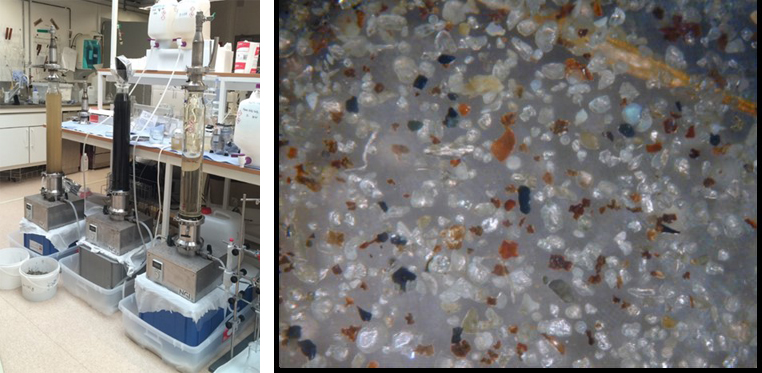
Figure 18
Analysis of plastics in sediments.
Left: Density separator. A column with fluid where the sample is entered. The plastic will float and heavier particles will sink.
Right: A sample shown under a microscope. Particle size is <500 µm.
Pictures: NGI.
8.2 Monitoring emission from blasted rock dumped in the sea
The main problem with blasted rock dumped in the sea is the discharge of microplastics. Often a physical barrier like for example a silt curtain (Figure 19) is placed outside the dumping area.
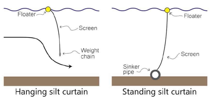
Figure 19
Top: Principles for hanging and standing silt curtains. Picture: J. of Waterway Port Coastal and Ocean Eng. (2015) 142(1):04015008.
Bottom: An installed silt curtain. Picture: www.tradeenviro.com.au
The silt curtain also stops spreading of sharp rock particles that could cause harm to fish. Monitoring is however still needed as physical barriers like silt curtains can reduce the emission of plastics from the dumped rock but not eliminate it.
- Monitoring by visual inspection from a boat during the process of dumping will help to identify spreading of plastics. At the same time the plastics can be removed (Figure 20).
- Monitoring by water sampling during the visual inspection of dumping will help to identify macro- and microplastics. Water samples can be analysed in laboratory as shown in Figure 18.
- Monitoring by visual inspections of a larger nearby coastal area is also possible by boat or by drones. This gives an overview if there is widespread spreading of plastics from blasted rock dumped in the sea (Figure 21).
- Monitoring of the seabed can be done using underwater photography or videos for macroplastics (such as by using a camera on an underwater drone or ROV or lowered from a boat). For monitoring of smaller plastics and microplastics, grab samples of sediment can be taken, and the microplastic can be separated from sediment using density separation.
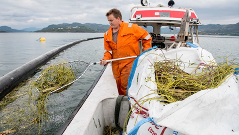
Figure 20
Removal of plastics can be done as a part of the monitoring operation. Picture: Jon Ingemundsen, Stavanger Aftenblad
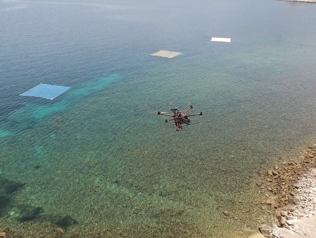
Figure 21
Detection of plastic waste with the use of drones. Picture: University of the Aegean, Greece.
8.3 Monitoring of emission from landfill with blasted rock
Placing the blasted rock on land in a landfill will substantially reduce the risk of spreading macro- and microplastics to the sea. The way the plastics can be spread to the sea from a landfill with blasted rock is by run-off water and windblown transport.
- Monitoring run-off water from a landfill can be done by establishing sampling points downstream the landfill in the direction towards the sea. The monitoring should be close to the point where the blasting takes place, and ideally in a culvert or drainage system where run-off water is accumulated. Analyses of water samples combined with visual observations will show if there is plastic that is spreading to the sea. If sand traps are in place to collect the runoff from the landfill, sand trap samples could also be sampled and analysed for microplastics.
- Monitoring wind-blown transport of plastics by visual inspection will give a general impression if there is any spreading. Methods for analysing plastics in air are still under development.
9. Replacement of plastics used in tunnelling and other blasting activities
In this chapter we discuss the possible replacement of plastics used in tunnelling and other blasting activities with other products, including plastics with less risk of emissions. To substitute the plastic with another material that is less harmful to the environment, or simply to reduce the plastic content of materials and processes, is in many cases the best and simplest way to avoid pollution from plastics.
9.1 Plastics used for blasting activities
Plastics are today used in a wide range of components in blasting activities. Chapter 4.3 gives an overview of where plastics are used.
9.1.1 Technical and safety requirements for blasting activities
There are several technical and safety requirements that need to be taken into account when replacement or reduction of plastics are considered for blasting activities.
An important part of the planning of a project is to optimize the product use with respect to environmental impacts. The environmental aspects also have to be weighed against safety, quality and cost efficiency of the project.
Important factors to consider are:
- Plastic wires of the electric and non-electric detonator systems must not be cut due to safety reasons. The plastic wires are manufactured in fixed lengths, meaning that often a longer wire has to be used than what actually is needed. Careful planning of the work is the best tool to prevent using unnecessary long wires. Wires that are left outside the boreholes will not burn and be left as plastic waste.
- Safety requirements need to be met when replacing plastic with another material. The replacing material must be at least as safe as plastic and approved by thorough product safety testing (regarding abrasion strength, pressure, water resistance and temperature limits for example).
- The length of the shock tubes has to be longer for blasting works in tunnels compared to blasting operations on the ground surface. This is a consequence of longer safety distances underground. But with accurate planning the individual length of each shock tube can be specified to the respective explosive instead of using a common standard length based on the required maximum distance.
9.1.2 Replacing plastics used in blasting activities with other materials
Many of the components that are used for blasting and which contain plastic can also be replaced with other material without compromising the technical and safety requirements.
Examples of such replacements are:
- Plastic connectors can be exchanged with smaller size connectors that do the same job and thereby reduce the amount of plastic that goes to the sea.
- Borehole plugs can simply be removed before blasting and recycled. Note that borehole plugs are only used for surface blasting.
- Using electronic detonators (with wire) (Figure 22) instead of electric or non-electric detonators may slightly reduce the amount of plastic waste. In addition to the higher price the plastic tubes of an electronic initiation system will sink instead of float on the water surface. This is due to the copper inside of the tube. Sinking makes the plastic waste “invisible” and more local, but harder to remove from the water areas. Sinking tubes will also take the plastic connectors with them (as long as they still hang together).
- Wireless electronic detonators are beginning to be available in the market and a wireless system will significantly reduce the amount of plastic waste. The challenges regarding a wireless detonator system are that they still have a much higher price and there is lack of knowledge/routines for use.
- Switching plastic cartridges of explosives with cartridges of a non-plastic material would reduce the risk of plastic waste. The cartridges will normally be fully destroyed from the explosion, but some exceptions may occur. Materials that have the same qualities as plastic needed for this purpose are not yet available. However, new materials are continuously being developed, so there might be alternatives in the future. The same applies, at least in theory, for detonating cords.
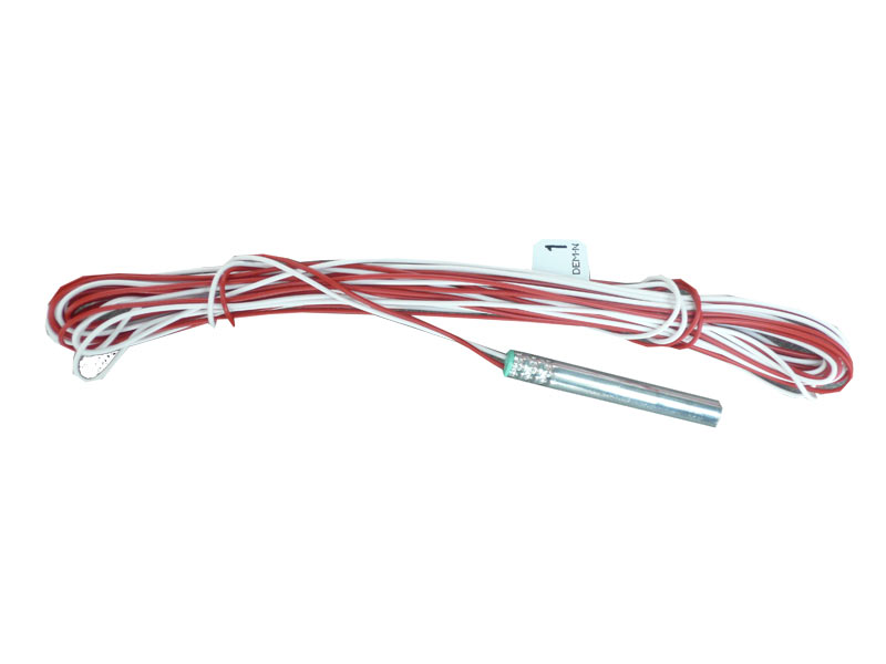
Figure 22
Electronic detonator with wiring. Picture from https://www.extraco.gr
9.2 Plastics used in shotcrete
Plastics are used in shotcrete for two different reasons. Macrofibres are used as reinforcement to increase the flexural strength while microfibres are used mainly to increase the resistance against spalling under the impact of fire. Spalling is when the shotcrete breaks off in fragments.
9.2.1 Technical requirements for flexural strength of plastic macrofibres and steel fibres in shotcrete
For reinforcement of shotcrete either steel fibres or plastic fibres are commonly used. Normally steel fibres are the default option for fibre reinforced shotcrete, but other fibres can be specified depending on requirements. The main reasons for using plastic macrofibres in applications where steel fibres with regard to strength and deformation characteristics can be replaced by plastic fibres are economic (plastic macrofibres can be used at a lower cost) but also that plastic fibres are resistant to corrosion.
The resistance to corrosion is of particular interest in aggressive environments like road tunnels with high humidity and possible exposure to thaw salt.
An inventory and field investigation of up to 50 years old Swedish shotcrete constructions, mainly tunnels, showed that steel fibres covered by concrete were well protected from corrosion, also steel fibres exposed in cracks in the shotcrete only showed corrosion to a limited extent. In general, the steel fibre reinforcement in the studied constructions were in good condition. However, constructions with wet sprayed shotcrete exposed to chlorides were missing in the investigation (Nordström, 1996).
In a continued study based on field investigation of shotcrete constructions 5–15 years old combined with accelerated laboratory testing it was concluded that steel fibre corrosion may pose a durability problem mainly for constructions exposed to high amounts of thaw salts and high humidity (Nordström, 2005). It was found that samples with long fibres corroded at a much higher rate than shorter ones and that stainless-steel fibres gave full protection during the time for accelerated exposures (corresponding to 50 years in field) whereas galvanized fibres took a longer time to initiate any corrosion. The continued study proposed that in the design state an extra amount of steel fibres is added, the thickness of the structure is increased or the fibre type is changed to a more corrosion resistant material to assure the long-term load-bearing capacity of the shotcrete.
A Swiss study (Kaufmann, 2014) came to the same conclusion that steel fibres in large cracks in shotcrete may corrode leading to a loss of the residual load bearing capacity (stainless steel fibres and galvanized fibres were not part of the test).
9.2.2 Replacing plastic macrofibres with steel fibres in shotcrete
With regard to technical requirements plastic fibres as reinforcement in shotcrete should be possible to exchange for steel fibres, also in aggressive environments. In aggressive environments one possibility is to use galvanized or stainless-steel fibres, another is to add an extra amount of fibres.
The cost for replacing polymer fibres with steel fibres is considerable. However, compared to the total cost for construction of a tunnel it is negligible. In the ongoing tunnelling projects on the Faroe Islands the increase in costs for using steel fibres instead of plastic fibres has only increased the cost for the whole tunnelling project with 0.1–0.15%.
Today, steel and plastic fibres are the types used as reinforcement in shotcrete. However, there probably are several other options, even if the knowledge and experience from other materials is limited so far. For example, carbon fibre mats for reinforcement of concrete structures exist on the market and carbon fibres can probably also be used as reinforcement of shotcrete. Other options are glass fibres and naturally occurring fibres, organic (fibres from plants) as well as inorganic (mineral fibres). However, further research and development is needed to gain knowledge and put new products on the market.
Replacing plastic fibres with steel fibres or new products does not affect the fact that fibres are lost due to rebound when the shotcrete are applied. Possible impact from the substitutes must therefore also be taken into account.
Finally, upstream environmental costs should also be considered in developing replacements. The environmental footprint of making a kg steel (e.g. CO2 emissions) is generally much larger than a kg of plastic; further, fibres made from recycled materials would have less of an environmental footprint than virgin materials.
9.2.3 Technical requirements of microfibres to prevent spalling
Microfibres of polypropylene are used to prevent spalling of concrete caused by fire (Figure 23). Spalling of concrete can occur as a consequence of rapid increase in temperature and serious damage has been reported from fires in tunnels (Silfwerbrand, 2012). It is well known that addition of microfibres of polypropylene can prevent spalling; addition of 2 kg fibres per m3 shotcrete is often used.
However, spalling can be prevented also by the concrete itself. According to recommendations from the Swedish Concrete Society, spalling will not occur if the water to cement ratio (vct) exceeds >0,6 and the content of powder (cement) is <350 kg/m3 (Svenska Betongföreningen 2011).
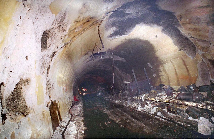
Figure 23
Spalling of concrete after the fire in the Mont Blanc tunnel in 1999. Picture: https://www.tunneltalk.com
9.2.4 Replacing plastic microfibres with other fibres to prevent spalling
To replace the microfibres of polypropylene with another fibre requires good knowledge of the mechanisms that prevent spalling. Probably a fibre with similar properties as the polypropylene microfibre is needed. However, it is not fully understood why the addition of microfibres increase the spalling resistance. A possible explanation is that the fibres melt (at 165 °C) and gasify (at 350 °C) which creates a pore structure through which also water vapor can be released and the build-up of high vapor pressures that otherwise can cause spalling is avoided. Contributing to this is also that the formation of micropores in the concrete increase when fibres are added and that cracks occur at the fibre ends when the fibres are heated (Statens Vegvesen 2013, Silfwerbrand 2012). Though plausible, this theory is not yet proven, and other properties may be as important, e.g. geometry, strength and deformation characteristics. Replacement of polypropylene microfibres with a non-plastic fibre therefore would imply further research and development including extended tests.
10. Case study: Faroe Islands – plastics in the sea due to placement of rock masses from tunnelling
In this chapter a case study from the Faroe Islands is presented from two ongoing tunnelling projects where plastics have ended up in the sea due to placement of rock masses.
10.1 Project description Eysturoyartunnilin and Sandoyartunnilin
On the Faroe Islands two new large tunnels are being established, Eysturoyartunnilin and Sandoyartunnilin, see Figure 24.
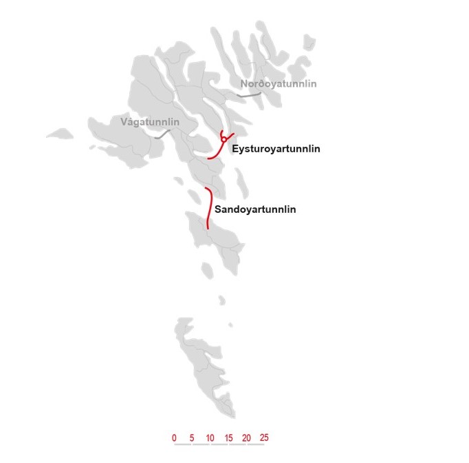
Figure 24
Map over the Faroe Island with the new tunnels Eysturoyartunnilin and Sandoyartunnilin marked in red. Map from Eystur- og Sandoyartunlar
The Eysturoyartunnilin (or Eysturoy Tunnel) is connecting the island of Streymoy to the island of Eysturoy through a sub-sea road tunnel (Figure 24). The tunnel is 11.2 km long, including a subsea roundabout (Figure 25). The tunnel will shorten the travel distance from Tórshavn to Runavík/Strendur from 55 km to 17 km. The drilling and blasting of the tunnel started in February 2017 and was finished June 2019. The tunnel is planned to open in 2020.
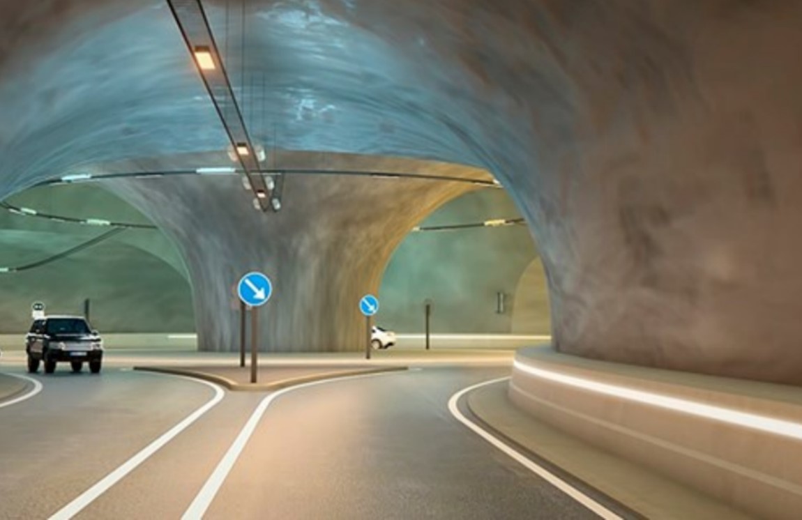
Figure 25
Subsea roundabout in Eysturoyartunnilin. From Eystur- og Sandoyartunlar
As soon as the drilling and blasting of Eysturoyartunnilin was finished in June 2019, the drilling and blasting of Sandoyartunnilin started. The tunnel will be 10.8 km long and drilling and blasting will take about two years. The whole tunnel is planned to be finished in 2023. The tunnel will connect Streymoy to the island of Sandoy, today there is only a ferry connection between the islands.
Total construction costs for both tunnels are estimated to be around 2.6 billion DKK, financed by 20% from the government and 80% from bonds. The tunnels will be repaid by road tolls. For further details about the tunnels, see Table 2.
| Eysturoytunnilin | Sandoytunnilin | |
| Length (m) | 11,240 | 10,800 |
| Slope (‰) | 50 | 50 |
| Lowest point (m) | -187 | -147 |
| Lanes | 2 | 2 |
| Standards | Norwegian Road Authorities standard | Norwegian Road Authorities standard |
| Construction time (years) | 3–4 (2017–2020) | 3–4 (2019–2023) |
| Vehicle per day | 5,620 | 350–400 |
Table 2
Details about the Eysturoy and Sandoy tunnels. From Eystur- og Sandoyartunlar
The blasted rock masses from the Eysturoytunnilin have been used for building roads on land and as fill material for road embankments on the seashore. Parts of the masses have also been used by local municipalities, as fill material to reclaim new land for industry purposes.
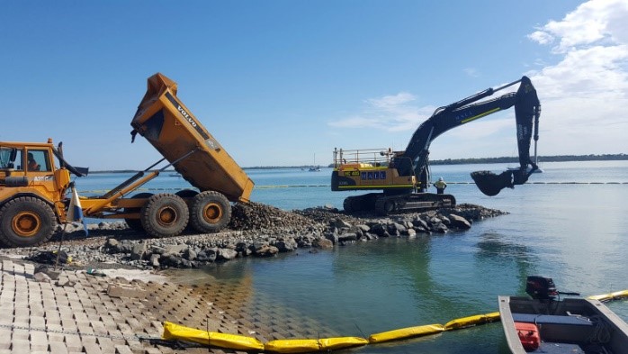
The construction of the roads leading to the two portals of the Eysturoytunnilin was made near the village of Hvítanes (north-east of Tórshavn) and in the village of Strendur and Runavík on Eysturoy, where they filled out a part of the sea near land (Figure 26). The placement of masses into the sea was done by split-hull barge and by trucks when masses were placed from the shore. In areas where the split-hull barge was used the water depth was 16 – 20 m.
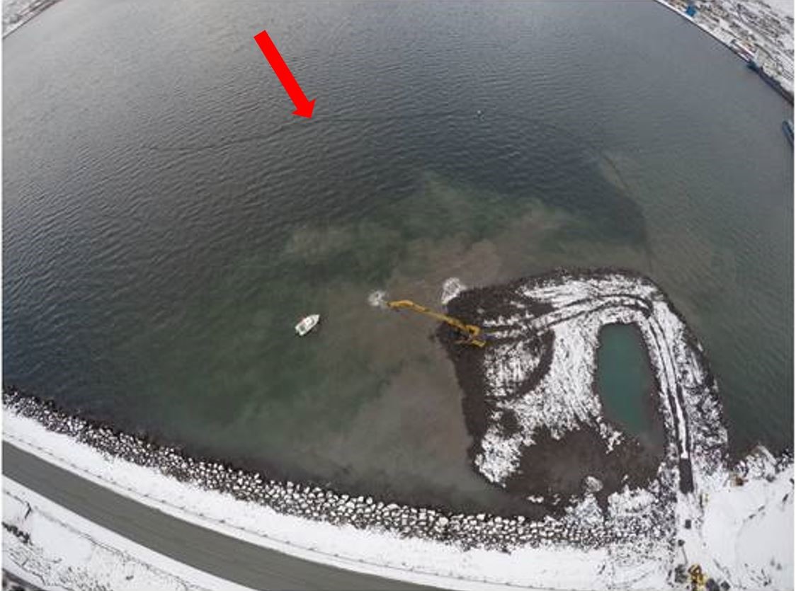
Figure 26
Filling blasted rock masses from Eysturoyartunnilin to the sea at Runavík. Note the boom to prevent spreading of plastics (red arrow). The main current direction is from the left to the right on the picture. Picture from Eystur- og Sandoyartunlar
For the Sandoyartunnilin, all rock masses will be used for various purposes on land and there are no plans today for filling masses into the sea. The project management are however expecting that during the project there could come requests from other projects for the masses to be used on land or in the sea.
It is estimated that 1 million m3 of rock (mainly basalt rock) will be taken out from each of the tunnels. Conventional drilling and blasting methods have been and will be applied, using shock tube detonators. The shock tubes consist of a plastic tube with an explosive powder on the tubing's inner surface. The detonation does not destroy the plastic tube. The plastic tubes will therefore be a part of the blasted rock when it is transported out of the tunnel.
As reinforcement in the shotcrete, steel fibres have been and will be used instead of plastic fibres due to the recent experiences from the Rogfast sub-sea tunnelling project in Norway. In the Rogfast infrastructure project plastic fibres were found to spread to the nearby shores as blasted rock masses were filled into the sea. Changing plastic fibres to steel fibres in the shotcrete in the Eysturoyartunnilin and Sandoyartunnilin projects is estimated to have increased the cost of the project with 150,000 DKK/km which is 0.1–0.15% of the total cost for the tunnelling projects.
10.1.1 Preventive measures
In addition to the rock itself, blasted rock masses contain leftover materials from the blasting procedure that contain plastics, such as firing cables (shock tubes), plastic connectors, detonators and borehole plugs.
When blasted rock from the Eysturoyartunnilin was filled out into the sea, it was observed that plastic parts (shock tubes) were released and spread in the sea. To prevent plastic parts from spreading an oil boom with a net reaching 1 m below the water surface was mounted partly around the work area (Figure 26). The purpose of the oil boom was to prevent plastics from spreading with the main current. Unfortunately, the oil boom was not efficient enough and shock tubes were washed up on the nearby shores. To avoid further spreading, procedures for removing plastics on the shores were established, and the plastics were collected manually once a week (Figure 27).
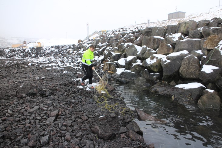
Figure 27
Collection of plastic shock tubes from the shore. Picture from Eystur- og Sandoyartunlar
As preparatory work for the Sandoyartunnilin it was looked further into how to prevent spreading of plastics when filling out blasted rock into the sea. The use of an aquaculture type of boom enclosure was proposed as a possible solution (Figure 28). The enclosure would have a high freeboard preventing the plastic from being washed over the boom. The plan was to re-use a fine-meshed smolt net from the fish farming industry. The net would go down to 1 m above the seafloor where it was going to be attached with anchors. There was also a possibility for boats to get in and out through a special opening in the enclosure (Figure 29). However, this solution has not been applied since it was decided not to fill rocks into the sea in this project, but it is a solution that is considered used in the future.
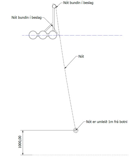
Figure 28
Illustration of aquaculture enclosure to be used to prevent plastic to spread out into the sea. Illustration from Eystur- og Sandoyartunlar
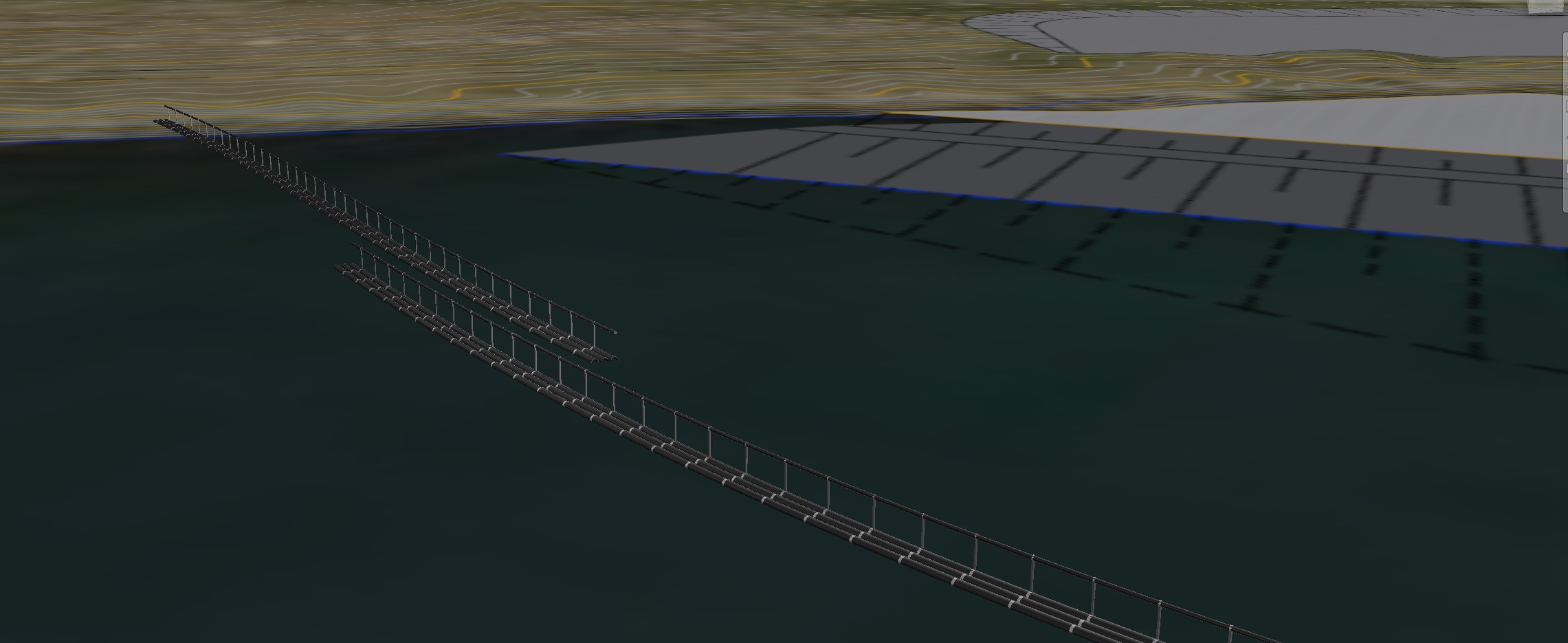
Figure 29
Illustration of the aquaculture enclosure in use. Illustration from producer of Sea-farming cages P/F KJ Hydralik, www.kj.fo, Faroe Islands
10.2 Lessons learnt from the project
The main lessons learned from the blasting and drilling for Eysturoyartunnilin with respect to the spreading of plastics to the sea are:
- Reducing the length of the plastic shock tube used for the blast as much as possible will minimise the total amount of plastics used.
- Less plastic shock tubes are washed out when the blasted rock is filled from the shore to the sea with a truck (Figure 30). An alternative is to use an excavator with a long arm, the important is to fill from the shore and outwards.
- More plastic shock tubes are washed out of the blasted rock when it is transported and dumped from a split-hull barge (Figure 31).
- Oil booms can be placed to prevent the floating plastic shock tubes from spreading.
- It is challenging to have a split-hull barge sailing in and out of the oil boom barrier. The barrier would have to be opened every time the barge is going in and out and the plastic can be spread through the opening. This was solved by having a part of the oil boom barrier permanently open and placed in such a way that the natural current was preventing the plastic from being transported out through the opening.
- The oil booms with a fine-meshed smolt-net reaching 1 m below the water surface that were used had limited positive effects as the plastic was seen passing the oil boom. The main reason was that the waves were washing the plastic over the oil boom.
- Even if procedures for systematic clean-up of the shorelines are established will some of the plastics most likely disappear to the sea.
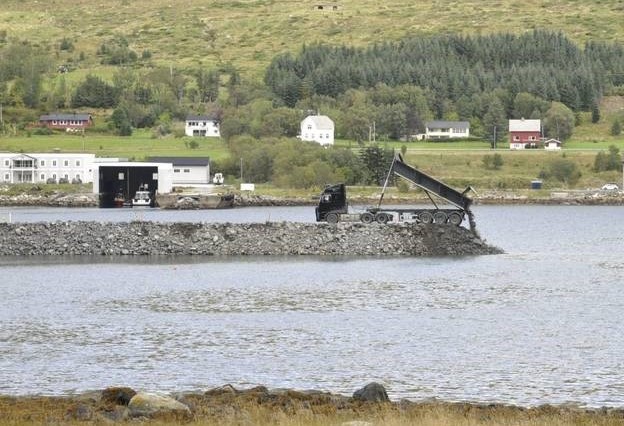
Figure 30
Filling of blasted rock from a truck. Picture from www.vestlandsnytt.no
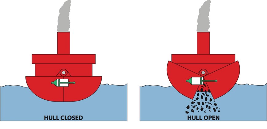
Figure 31
Schematic figure of a split-hull barge. Picture from www.foxvalve.com
11. Summary and recommendations
It is with relatively simple measures possible to prevent a substantial fraction of plastics from blasted rock and shotcrete from entering the sea. We have below listed a summary of the most important suggested measures in the report which should contribute to an estimated minimum of 75% reduction of plastic emissions from blasted rock and shotcrete to the sea.
We have divided the measures into:
- Avoidance – it is possible to minimise or eliminate plastic by investigating options to avoid or minimise blasting at an early stage of the project
- Substitution – it is possible to substitute plastic fully or partially with other materials
- Impact reduction – it is possible to reduce the impact of plastics by controlling the plastic and avoiding the plastic from spreading
11.1 Avoidance
The first question should be what technology that should be used to establish the tunnel; blasting or a tunnel boring machine (see Chapter 3). With the exclusive use of a TBM, all plastics that would have been generated from blasting and shotcrete can be avoided.
The main objective if blasting is chosen should be that the use of plastic should be minimised. When the plastic once has entered into the blasting or shotcrete operation it is very difficult to separate the plastic afterwards.
Careful planning is vital to avoid plastics pollution from tunnelling (blasting and shotcrete activities). By introducing the question at an early stage in the project it is possible to avoid or minimise the impact of plastics to the environment. The planning should also consider taking into account what cleaning up of plastic that is spread to the sea will cost and the negative reputation of the project plastics pollution would give.
It has to be underlined that safety can of course never be compromised and always has to have the highest priority.
Training and education of the blasting team will help to motivate them and get a better understanding of the importance to avoid plastics pollution. This includes an increased focus on the environment and incentives, also economical, to not spread plastic.
11.2 Substitution
With substitution is meant that the plastic is fully or partially replaced with other (preferably) more environmentally friendly materials.
Suggestion 1: Instead of detonators with firing cables that are currently mostly used, electronic wireless detonators can be used. Electronic wireless detonators have no lead wires.
Effect: Due that electronic wireless detonators have no plastic firing cables, the amount of plastic from a blasting operation will be reduced drastically.
Remark: Today the electronic wireless detonators are more expensive than detonators with lead wires. They are yet not in use in Nordic tunnelling.
Suggestion 2: Blasthole casings made from paperboard (Figure 32) can be used instead of plastic casings.
Effect: Will fully exchange the use of plastics for protecting for the blasthole.
Remark: Blasthole casings made from paperboard are available on the market.
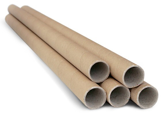
Figure 32
Blasthole casings can be made from paperboard. Picture from www.eu.neuland.com
Suggestion 3: Reduce the amount of plastics used. For example, reduce the amount and length of the detonators, size of plastic connectors.
Effect: Will reduce the amount plastics used for blasting.
Remark: There are already smaller plastic connectors on the market.
Suggestion 4: Substitute the plastic macrofibres in shotcrete with steel fibres.
Effect: Will reduce the amount plastics in rebound from shotcrete.
Remark: It implies an increased cost, but it is almost negligible compared to the total cost for the tunnel. The Norwegian Road Administration has already set use of steel fibres as a requirement in tunnelling works. There is some concern about “upstream” environmental impacts of steel production vs plastic fibre production, as these have not been considered in replacement strategies. Further coupled life-cycle analysis and environmental risk assessment is therefore recommended for the substitution in different tunnel scenarios.
Suggestion 5: Exclude or reduce plastic microfibres from shotcrete. In many cases spalling can instead be prevented by using concrete with appropriate properties.
Effect: Will reduce the amount plastics in rebound from shotcrete.
Remark: Depending on other requirements on the shotcrete, it is probably not always possible. Also, today more microfibres are added than normally is needed to avoid spalling.
11.3 Impact reduction
Impact reduction of plastics will help to control the plastic and avoid the plastic from spreading.
Suggestion 1: Utilisation of blasted rock in constructions on land, or if not possible, local landfilling.
Effect: Utilising blasted rock on land will drastically reduce the possibility for plastics to spread to the sea.
Remark: There is not always possibilities to reuse blasted rock on land or finding suitable sites for landfilling; though it is recommended to consult with local companies that accept or are open to finding uses for blasted rock. If landfilling, local sites are preferred to save transportation costs and emissions.
Suggestion 2: Use of temporary flexible barriers based on booms and nets.
Effect: Can to a significant extent prevent spreading of plastics.
Remark: There is need for frequent collection of floating plastics and maintenance of the barriers and nets. An adequate construction of the barrier is essential for the function. Active (daily) inspection of the barrier along with collection of plastic is recommended. Avoid blasting on bad weather days to lower the risk of waves and wind blowing plastic over the barriers.
Suggestion 3: Construction of an embankment surrounding the disposal area prior to filling blasted rock containing plastics.
Effect: Can to a significant extent prevent spreading of plastics.
Remark: The embankment should be built with rock containing as little plastic as possible. Frequent collection of floating plastics inside the barrier is necessary.
Suggestion 4: Use (sinking) plastics with a density greater than water and plan for sediment capping in the case of using blasted rock for offshore construction or deep-water landfills.
Effect: Will cause plastics to remain deposited with blasted rock mass, or under sediment cap.
Remark: Plastics that sink in water (e.g. made of nylon, PVC, or metal impregnated plastics) may not be available for all blasting products. Capping is nevertheless recommended to prevent trapped low-density plastics from being released due to erosion or sediment resuspension processes.
12. References
Arp, H.P., 2018. Hva skjer når plast fra tunnelbransjen havner i havet? Presentation given at Tunneldagene 2018. Thon Hotel Arena, Lillestrøm, 11.04.2018.
Breyholtz, B., 2018. Håndtering av plastforurensning i sprengstein. Presentation given at Miljøringen, 14. March 2018. https://miljoringen.no/wp-content/uploads/2018/03/Dag-1-09-Bente-Breyholtz.pdf
Breyholtz, B., 2017. Testforsøk - spredning av plast i sjø fra utfylte tunnelmasser skutt med elektroniske tennere. Aldersundet - Rassikringsprosjekt Rv 17 Liafjell. Norconsult oppdragsnr 5144240. Dokumentnr. YM-119-NO. https://www.fylkesmannen.no/globalassets/fm-rogaland/dokument-fmro/miljo/hoyringsdokument/statens-vegvesen/vedlegg-9---testforsok---elektroniske-skyteledninger-i-utfyllingsmasser.pdf
British Plastics Federation, 2019. Nylons (Polyamide). https://www.bpf.co.uk/plastipedia/polymers/polyamides.aspx
China Railway Engineering Group, 2016. Rectangular and circular TBMs challenges & solutions, in underground construction. Sydney: CREG, 19th May 2016.
Choy, C.S., Robison, B.H., Gagne, T.O., Erwin, B., Firl, E., Halden, R.U., Hamilton, J.A., Katija, K., Lisin, S.E., Rolsky, C. & Van Houtan, K.S., 2019. The vertical distribution and biological transport of marine microplastics across the epipelagic and mesopelagic water column. Nature. Scientific Reports volume 9, Article number: 7843 (2019). https://www.nature.com/articles/s41598-019-44117-2#citeas
Goméz-Bergström and Bahr, 2015. Konventionell sprängning eller fullortsborrning som tunneldrivningsmetod? KTH, MJ153x Examensarbete.
Hildonen, H., 2019. Plastforsøpling globalt, i Norge og på anleggsplassen. Fremtidens tunnel- og anleggsdrift – Miljøkravene er her. Foredrag. http://nff.no/wp-content/uploads/2019/01/19-Hildonen.pdf
Kaufmann, J.P., 2014. Durability performance of fiber reinforced shotcrete in aggressive environment. Proceedings of the world tunnel congress, 2014.
Knutsen, H., Cyvin, J., Totland, C., Lilleeng, Ø., Wade, E.J., Castro, V., Pettersen, A., Møskeland, T., Laugesen, J., Arp, H.P., 2020. Enrichment of microplastic by tube-dwelling, suspension feeding polychaetes on the sediment surface: a case study from the Norwegian Continental Shelf. Submitted to J. of Marine Environmental Research.
Likhosherskaya, I. and Nyembwe, K.R., 2012. Spredning av plastfibre fra sprøytebetong. Kartlegging av spredningsmåte og mottiltak. Statens vegvesens rapporter nr 146, 20.07.2012
Miljødirektoratet 2018. Problemer med plast ved utfylling av sprengstein i sjø. Faktaark M-1085.
Nordström, E., 2005. Durability of Sprayed Concrete. Steel fibre corrosion in cracks. Luleå University of Technology, Doctoral Thesis 2005:2.
Nordström, E., 1996. Sprutbetongs beständighet. Inventering. Swedish Rock Engineering Research, SveBeFo Rapport 26.
Norsk forening for Fjellsprengningsteknikk (NFF), 2018. The Tunnel Statistics 2018. Published 16th of November 2018. http://nff.no/wp-content/uploads/2019/03/The-Tunnel-Statistics-2018.pdf
Norsk forening for Fjellsprengningsteknikk, 2019. Elektroniske tennere i tunnel. Teknisk rapport nr. 19. http://nff.no/wp-content/uploads/2019/04/Teknisk-rapport-nr.-19_30.04.19.pdf
PlasticsEurope, 2019. Plastics- the Facts 2019. https://www.plasticseurope.org/application/files/9715/7129/9584/FINAL_web_version_Plastics_the_facts2019_14102019.pdf
SGI, 2016. In-situ capping of contaminated sediments. Method overview. The Swedish Geotechnical Institute, Linköping, Sweden. SGI Publication 30-1E. https://www.swedgeo.se/en/research--learning/publikationer/sgi-publikation/in-situ-capping-ov-contaminated-sediments---method-overview/
Silfwerbrand, 2012, Brandsäkring / Brandsikring ved brug af plastfibre. Lecture at Dansk Betonforening 10. okt 2012, København.2011)
SMED (Svenska MiljöEmissionsData), 2019. Kartläggning av plastflöden i Sverige. Råvara, produkter, avfall och nedskräpning. Rapport Nr 01 2019. https://smed.se/avfall/4520
Statens vegvesen 2020. Vegtunneler. Normal. Håndbok N500. https://www.vegvesen.no/_attachment/61913
Statens vegvesen, 2019. Miljøutfordringer med sprengsteinsmasser, Rogfast. Presentasjon av Merete Landsgård, Ytre miljø Rogfast, 11. apr 2019. https://www.fylkesmannen.no/globalassets/fm-rogaland/dokument-fmro/miljo/arrangementsdokument/tiltak-i-sjo-seminar/6.-miljoskade-i-sjo---statens-vegvesen-region-vest.pdf
Statens vegvesen, 2013. Brannsikringsfibre. Potensielle spredningsveier til omliggende miljø og tiltak mot spredning. Statens vegvesens rapporter nr. 140. https://www.vegvesen.no/en/professional/focus-areas/research-and-development/completed-projects/norwat/publications/_attachment/464583?_ts=13e30f54af0&fast_title=SVV+rapport+140.pdf
Statens vegvesen 2012. Spredning av plastfibre fra sprøytebetong. Kartlegging av spredningsmåte og mottiltak. Statens vegvesen report no. 146. https://www.vegvesen.no/fag/fokusomrader/forskning+og+utvikling/Avsluttede+FoU-program/NORWAT/Publikasjoner/_attachment/365838?_ts=1391fa51c30&fast_title=Spredning+av+plastfibre+fra+spr%C3%B8ytebetong.pdf
Svenska Betongföreningen, 2011, Betong och brand. Rekommendationer för att förhindra spjälkning i anläggningskonstruktioner. Betongrapport 16-2011. Interimsrapport.
About this publication
Plastics in the sea from blasted rock - prevention and measures
Jens Laugesen, Veera Komulainen, Marion Børresen, Pär Elander, Hans Peter Arp, Teitur Samuelsen and Einar Brimnes
ISBN 978-92-893-6656-4 (PDF)
ISBN 978-92-893-6657-1 (ONLINE)
http://dx.doi.org/10.6027/temanord2020-520
TemaNord 2020:520
ISSN 0908-6692
© Nordic Council of Ministers 2020
Disclaimer
This publication was funded by the Nordic Council of Ministers. However, the content does not necessarily reflect the Nordic Council of Ministers’ views, opinions, attitudes or recommendations.
Rights and permissions
This work is made available under the Creative Commons Attribution 4.0 International license (CC BY 4.0) https://creativecommons.org/licenses/by/4.0.
Translations: If you translate this work, please include the following disclaimer: This translation was not pro-duced by the Nordic Council of Ministers and should not be construed as official. The Nordic Council of Ministers cannot be held responsible for the translation or any errors in it.
Adaptations: If you adapt this work, please include the following disclaimer along with the attribution: This is an adaptation of an original work by the Nordic Council of Ministers. Responsibility for the views and opinions expressed in the adaptation rests solely with its author(s). The views and opinions in this adaptation have not been approved by the Nordic Council of Ministers.
Third-party content: The Nordic Council of Ministers does not necessarily own every single part of this work. The Nordic Council of Ministers cannot, therefore, guarantee that the reuse of third-party content does not in-fringe the copyright of the third party. If you wish to reuse any third-party content, you bear the risks associ-ated with any such rights violations. You are responsible for determining whether there is a need to obtain per-mission for the use of third-party content, and if so, for obtaining the relevant permission from the copyright holder. Examples of third-party content may include, but are not limited to, tables, figures or images.
Photo rights (further permission required for reuse):
Any queries regarding rights and licences should be addressed to:
Nordic Council of Ministers/Publication Unit
Ved Stranden 18
DK-1061 Copenhagen
Denmark
pub@norden.org
Nordic co-operation
Nordic co-operation is one of the world’s most extensive forms of regional collaboration, involving Denmark, Finland, Iceland, Norway, Sweden, and the Faroe Islands, Greenland and Åland.
Nordic co-operation has firm traditions in politics, economics and culture and plays an important role in European and international forums. The Nordic community strives for a strong Nordic Region in a strong Europe.
Nordic co-operation promotes regional interests and values in a global world. The values shared by the Nordic countries help make the region one of the most innovative and competitive in the world.
The Nordic Council of Ministers
Nordens Hus
Ved Stranden 18
DK-1061 Copenhagen
pub@norden.org
Read more Nordic publications on www.norden.org/publications